60C5D11
5-46
1
2
3
4
5
6
7
8
9
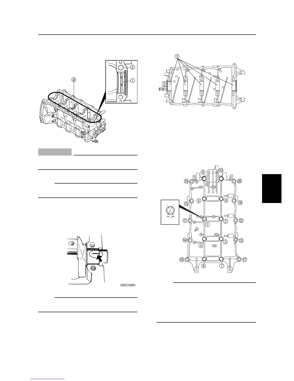
3. Install half of the bearings (grooved bear-
ings)
1
and the crankshaft into the cylin-
der body
2
.
CAUTION:
Install the bearings in their original posi-
tions.
NOTE:
Install the unified thrust bearing at the posi-
tion
a
shown.
4. Put a piece of Plastigauge (PG-1) on
each main journal parallel to the crank-
shaft.
NOTE:
Do not put the Plastigauge (PG-1) over the
oil hole in the main journals of the crankshaft.
5. Install the remaining half of the bearings
(plain bearings)
3
into the crankcase.
6. Install the crankcase onto the cylinder
body and apply engine oil onto the
threads of the crankcase bolts.
7. Tighten the crankcase bolts to the speci-
fied torques in two stages and in the
sequence shown.
NOTE:
• Do not move the crankshaft until the main
journal oil clearance measurement has
been completed.
• Make a mark on the crankcase and crank-
case bolts, and then tighten the M10 bolts
60° from the mark.
S60C5910
S60C5925
S60C5930
60°
Cylinder body