BRKT
Bracket unit
7-91
60C5D11
Checking the fuse
1. Check the fuse for continuity. Replace if
there is no continuity.
Checking the power trim and tilt
relay
1. Connect the digital circuit tester between
power trim and tilt relay terminals
1
and
2
.
2. Connect the light green (Lg) lead or sky
blue (Sb) lead
3
to the positive battery
terminal and the black (B) lead
4
to the
negative battery terminal as shown.
3. Check for continuity between terminals
1
and
2
. Replace if there is no continu-
ity.
4. Disconnect the black (B) lead
4
. Check
for continuity between terminals
1
and
2
. Replace if there is continuity.
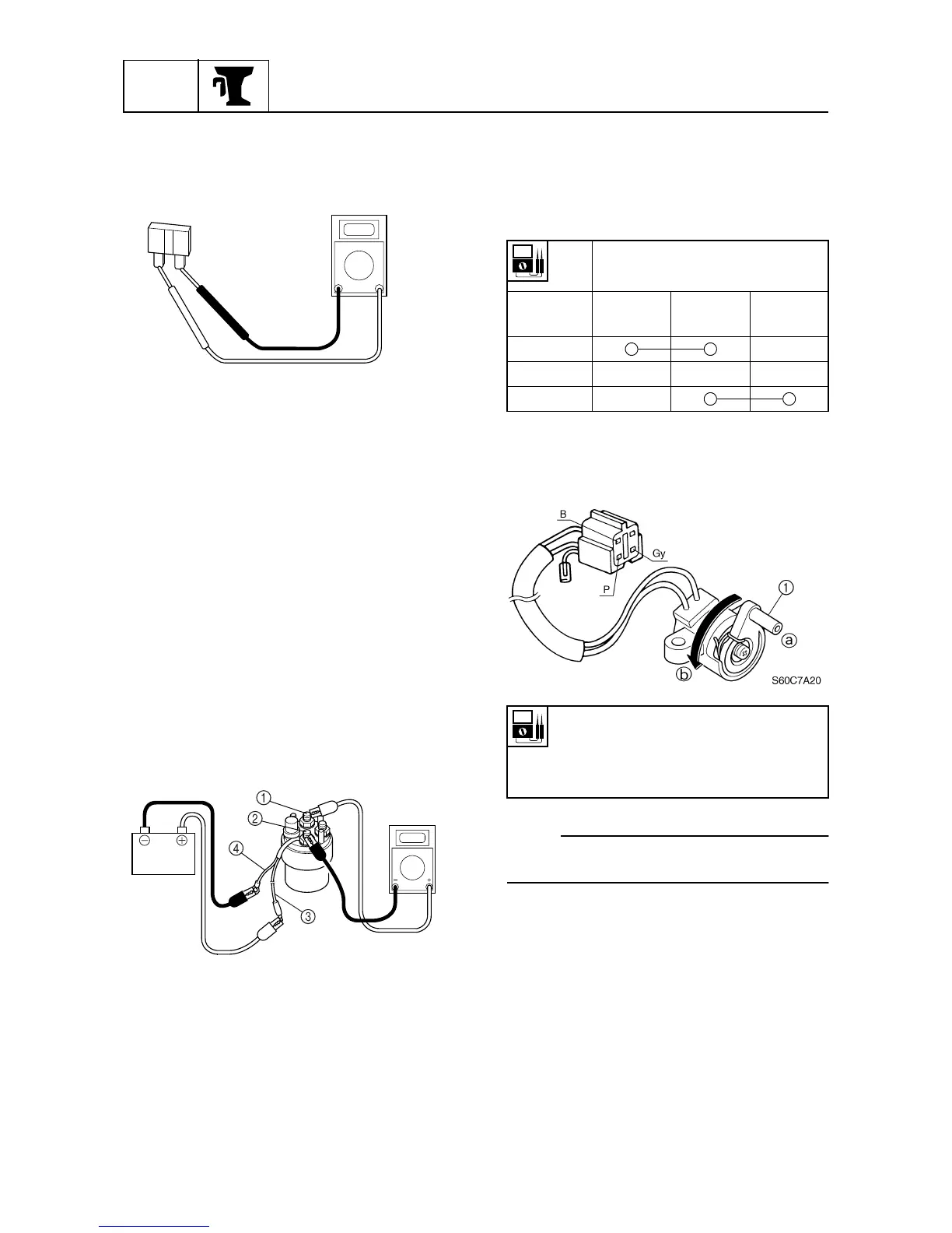
Checking the power trim and tilt
switch/trailer switch
1. Check the power trim and tilt
switch/trailer switch for continuity.
Replace if out of specification.
Checking the trim sensor
1. Measure the trim sensor resistance.
Replace if out of specification.
NOTE:
Turn the lever
1
and measure the resistance
as it gradually changes.
S60C7995
S60C7A05
Lead color
Switch
position
Sky blue
(Sb)
Red (R)
Light green
(Lg)
Up
Free
Down
Trim sensor resistance:
Pink (P) – Black (B)
9–11
Ω
at 20 °C (68 °F)
a
238.8–378.8 Ω at 20 °C (68 °F) b