ELEC
Electrical systems
– +
8-21
60C5D11
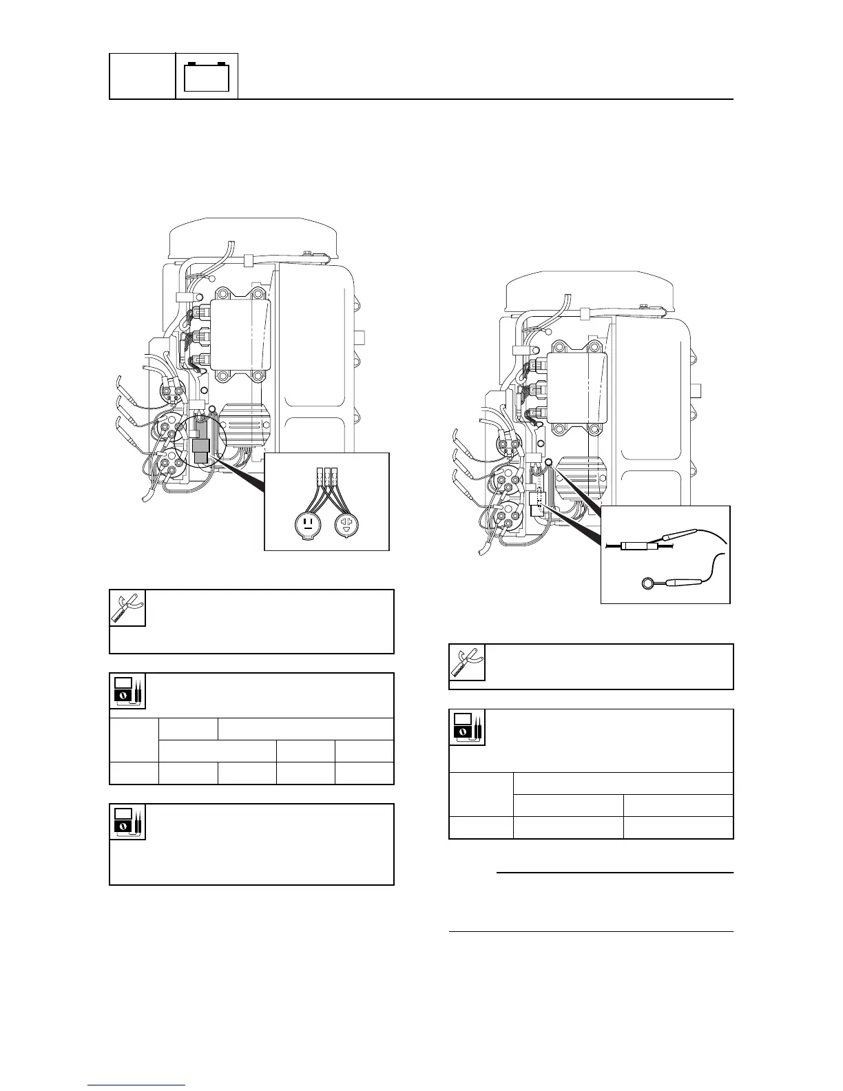
Checking the lighting coil
1. Measure the lighting coil output peak
voltage. Replace the lighting coil if below
specification.
Checking the Rectifier Regulator
1. Measure the Rectifier Regulator output
peak voltage. If below specification, mea-
sure the lighting coil output peak voltage.
Replace the Rectifier Regulator if the out-
put peak voltage of the lighting coil is
above specification.
NOTE:
Disconnect the output lead (red lead) of the
Rectifier Regulator when measuring the out-
put peak voltage.
Digital circuit tester: 90890-03174
Peak voltage adaptor: 90890-03172
Test harness (3 pins): 90890-06770
Lighting coil output peak voltage:
White (W) – White (W)
r/min
Unloaded
Loaded
Cranking 1,500 3,500
DC V 7.5 8.0 15.5 15.5
Lighting coil resistance (use as
reference):
White (W) – White (W)
0.32–0.48
Ω
at 20 °C (68 °F)
S60C8130
Digital circuit tester: 90890-03174
Peak voltage adaptor: 90890-03172
Rectifier Regulator output peak
voltage:
Red (R) – Black (B)
r/min
Unloaded
1,500 3,500
DC V 17.5 19.0
S60C8150