60C5D11
5-50
1
2
3
4
5
6
7
8
9
NOTE:
• Make sure that the large, flat side
c
of the
connecting rod faces towards the flywheel
magnet side of the crankshaft.
• Apply engine oil to the connecting rod cap
and connecting rod bolt.
8. Install half of the bearings (plain bear-
ings)
B
into the crankcase.
9. Apply Gasket Maker
®
to the mating sur-
face of the crankcase.
NOTE:
Do not get any Gasket Maker on the journal
bearings.
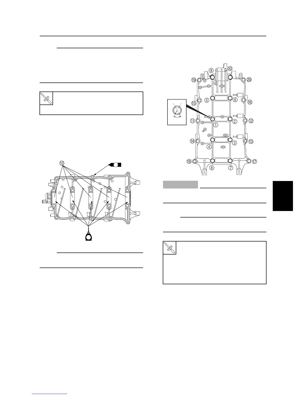
10. Install the crankcase bolts, and then
tighten them to the specified torques in
two stages and in the sequence shown.
CAUTION:
The oil seals must be installed before
tightening the crankcase bolts.
NOTE:
Apply engine oil to the crankcase bolts before
installation.
T
R
.
.
Connecting rod bolt
A
:
1st: 18 N·m (1.8 kgf·m, 13 ft·lb)
2nd: 90°
S60C5B40
E
GM
GM
Crankcase bolt (M10):
1st: 19 N·m (1.9 kgf·m, 14 ft·lb)
2nd: 60°
Crankcase bolt (M8):
1st: 14 N·m (1.4 kgf·m, 10 ft·lb)
2nd: 28 N·m (2.8 kgf·m, 20 ft·lb)
S60C5930
60°
Cylinder body