4-13
1
2
3
4
5
6
7
8
9
10
FUEL
FUEL INJECTORS AND INTAKE MANIFOLD
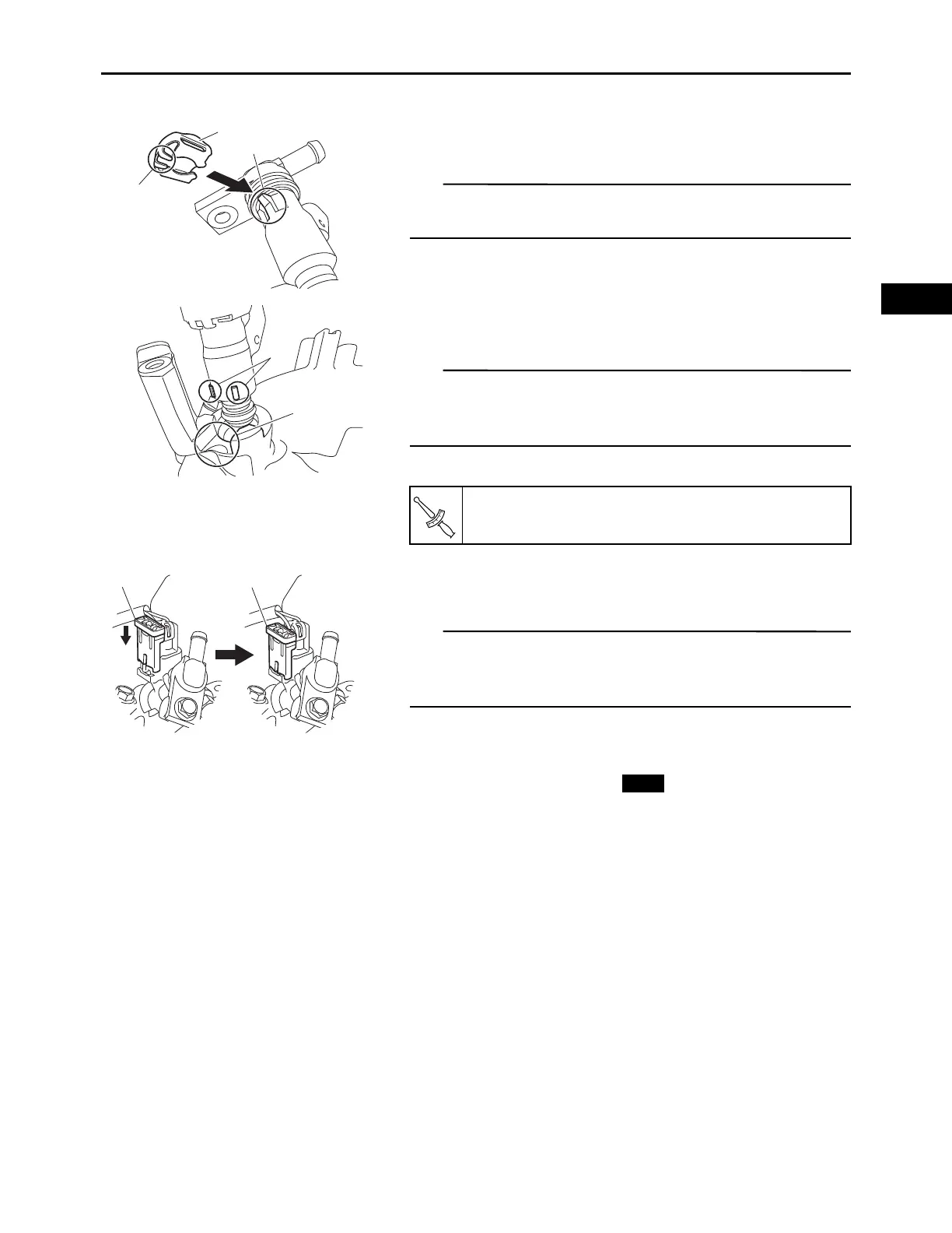
2.
Install:
• Retainer “1”
Engage the claw “a” of the retainer with the projection “b”
on the fuel injector, and install to the fuel injector.
3.
Install:
• Fuel injector
Engage the projection “a” on the fuel injector with the
groove “b” in the intake manifold, and install to the intake
manifold.
• Inlet pipe bolts
4.
Connect:
• Fuel injector lead coupler
Insert the coupler securely, slide the coupler cover “a”
downward as shown in the illustration, and then lock the
coupler.
5.
Install:
• Hose clamp (Clic-R)
(Refer to “INSTALLING THE OIL COOLER” on
page 3-6)
• Fuel injector pipe 1
• Fuel injector pipe 2
6.
Install:
• Ignition coil
(Refer to “IGNITION COILS” on page 3-10)
• Throttle body assembly
(Refer to “THROTTLE BODY ASSEMBLY” on page
4-6)
• Fan case and fan
(Refer to “CASE AND FAN” on page 3-11)
• Oil cooler
(Refer to “OIL COOLER” on page 3-5)
• Low-pressure fuel pump
(Refer to “FUEL PUMPS” on page 4-1)
Inlet pipe bolt:
9 N·m (0.9 kgf·m, 6.5 lb·ft)