5-30
1
2
3
4
5
6
7
8
9
10
ELECTRICAL
ELECTRICAL COMPONENTS
▼▼▼▼▼▼▼▼▼▼▼▼▼▼▼▼▼▼▼▼▼▼▼▼▼▼▼▼▼▼▼▼▼▼▼▼▼▼▼▼▼
a. Connect the digital circuit tester () to the throttle
position sensor terminals as shown.
b. Measure the throttle position sensor maximum
resistance.
▲▲▲▲▲▲▲▲▲▲▲▲▲▲▲▲▲▲▲▲▲▲▲▲▲▲▲▲▲▲▲▲▲▲▲▲▲▲▲▲▲
3.
Install:
• Throttle body assembly
CHECKING THE CRANKSHAFT POSITION
SENSOR
1.
Remove:
• Fan case cover
• Grass screen
• Fan case
(Refer to “CASE AND FAN” on page 3-11)
2.
Check:
• Crankshaft position sensor resistance
Out of specification Replace the crankshaft posi-
tion sensor.
▼▼▼▼▼▼▼▼▼▼▼▼▼▼▼▼▼▼▼▼▼▼▼▼▼▼▼▼▼▼▼▼▼▼▼▼▼▼▼▼▼
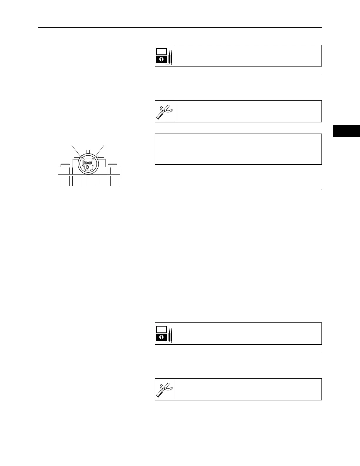
a. Connect the digital circuit tester () to the crank-
shaft position sensor coupler as shown.
Resistance:
3.0–7.0 k
Model 88 Multimeter with tachometer:
YU-A1927
• Positive tester probe
Terminal “a”
• Negative tester probe
Terminal “b”
Crankshaft position sensor resistance:
3.0–7.0 k
Model 88 Multimeter with tachometer:
YU-A1927