5-9
1
2
3
4
5
6
7
8
9
10
ELECTRICAL
FUEL INJECTION SYSTEM
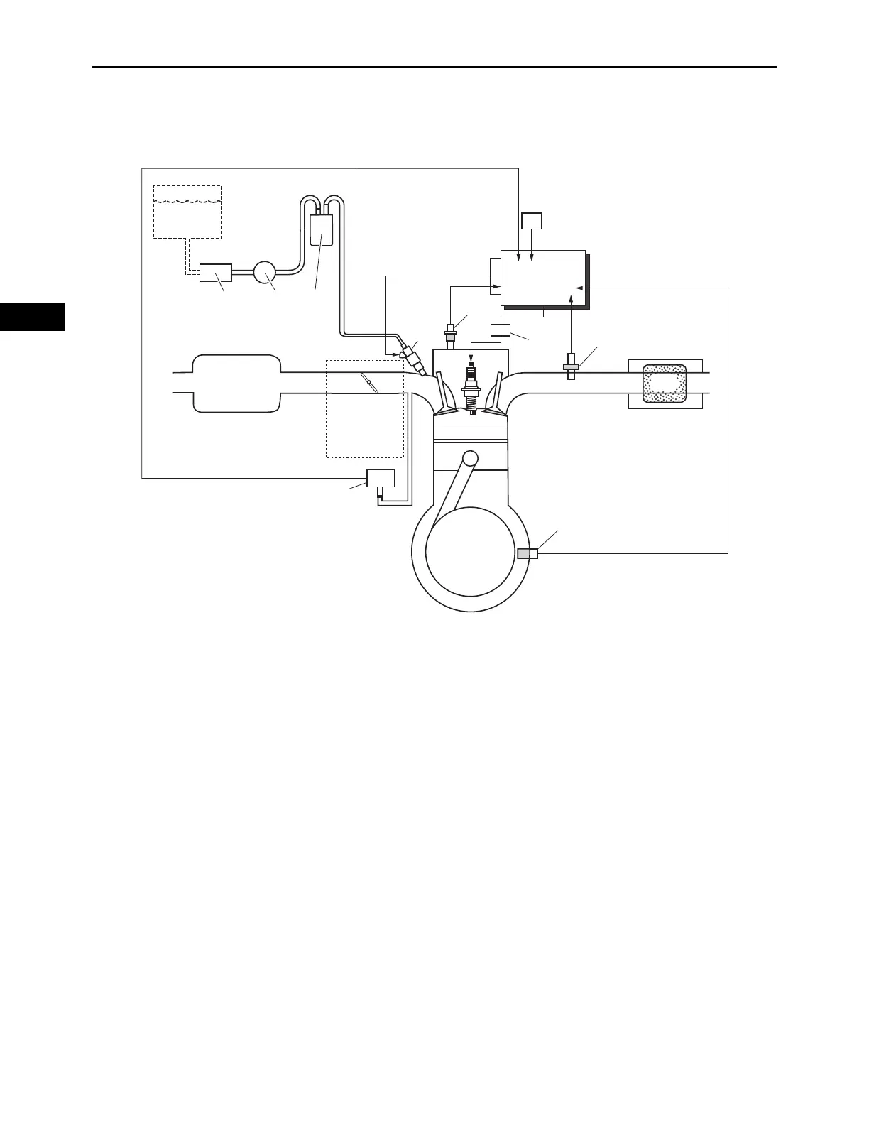
FUEL INJECTION DIAGRAM
1. Fuel filter 8. O
2
sensor
2. Fuel pump (low pressure) 9. Engine temperature sensor
3. Fuel pump (high pressure) 10.Crankshaft position sensor
4. Fuel injector 11.Throttle body
5. ECU (Engine Control Unit) 12.Manifold absolute pressure sensor
6. Throttle position sensor 13.Air filter case
7. Ignition coil 14.Muffler
A. Fuel system
B. Air system
C. Control system
3
13
B
11
12
10
9
8
A
4
5
C
7
6
14
21