5-2
1
2
3
4
5
6
7
8
9
10
ELECTRICAL
CIRCUIT DIAGRAM
Color code
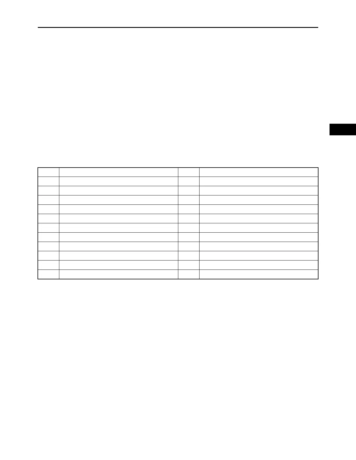
1. ECU (Engine Control Unit) 14.Rollover switch
2. Stator coil assembly 15.FI diagnostic tool coupler
3. Rectifier/regulator 16.Engine temperature sensor
4. Fuse (30 A) 17.Manifold absolute pressure sensor
5. Fuse (10 A) 18.Throttle position sensor
6. Fuse (10 A) 19.O
2
sensor
7. Oil pressure switch 20.Crankshaft position sensor
8. Starter relay 21.High-pressure fuel pump
9. Starter motor 22.Ignition coil #2
10.Battery 23.Ignition coil #1
11.Main switch 24.Fuel injector #1
12.Mil light 25.Fuel injector #2
13.Oil warning light
B Black G/R Green/Red
Br Brown G/W Green/White
G Green G/Y Green/Yellow
Gy Gray L/O Blue/Orange
L Blue L/W Blue/White
O Orange P/L Pink/Blue
R Red R/L Red/Blue
V Violet R/W Red/White
W White R/Y Red/Yellow
Y Yellow W/B White/Black
B/W Black/White W/R White/Red
Br/G Brown/Green Y/L Yellow/Blue