Parameter Details
5
5.14 Z: Bypass Parameters
YASKAWA SIEPYAIH6B01A HV600 AC Drive Bypass Technical Reference 447
41: OverPressure Switch (NC)
Setting Value Function Description
41 OverPressure Switch (NC) Stops the drive from running and shows “OverPressure” on the keypad.
42: Low Suction Switch (NC)
Setting Value Function Description
42 Low Suction Switch (NC) Stops the drive from running and shows “Low Suction” on the keypad.
43: Vibration Switch (NC)
Setting Value Function Description
43 Vibration Switch (NC) Stops the drive from running and shows “Vibration” on the keypad.
44: Emergency Override Drive (REV)
Setting Value Function Description
44 Emergency Override Drive
(REV)
The bypass controller stays in this state even if the drive faults or is unavailable.
The preset speed is equal to Z1-10.
45: Serial Hardware Test (RS-485)
Setting Value Function Description
45 Serial Hardware Test (RS-
485)
46: Low City Pressure
Setting Value Function Description
46 Low City Pressure Indicates that sufficient or insufficient pressure is present on the inlet to the pump. Used mainly for pressure booster situations.
47: Motor Preheat
Setting Value Function Description
47 Motor Preheat Sets the command to apply the motor pre-heat current.
■ Z2-23 to Z2-26 Digital Output 7 to 10 Function Selection
The drive has 4 digital output terminals. Refer to Table 5.72 for default settings and functions.
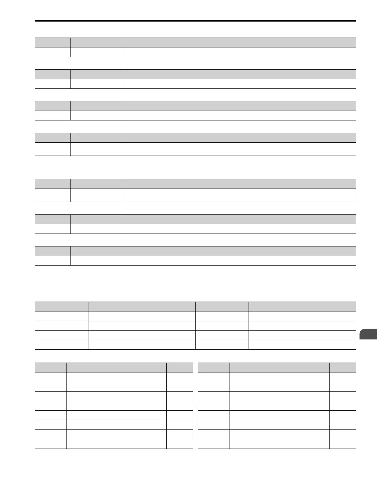
Table 5.72 Digital Output Default Settings and Functions
No. Name Default Function
Z2-23 Digital Output 7 (TB1 1~3) 7 RUN Active
Z2-24 Digital Output 8 (TB1 4~6) 10 HAND mode Active
Z2-25 Digital Output 9 (TB1 7~9) 12 Auto mode Active
Z2-26 Digital Output 10 (TB1 10~12) 15 Fault Active
Table 5.73 Digital Output Setting Values
Setting Value Function Reference
0 Serial Communication Control
448
1 K1 Drive Input Contactor
448
2 K2 Drive Input Contactor
448
3 K3 Bypass Contactor
448
4 K4 Motor 1 Contactor
449
5 K5 Motor 2 Contactor
449
6 READY
449
7 RUN Active
449
Setting Value Function Reference
8 Drive RUN active
449
9 Bypass RUN active
449
10 HAND mode Active
449
11 OFF mode Active
449
12 Auto mode Active
449
13 Drive Mode Selected
450
14 Bypass Mode Selected
450
15 Fault Active
450