6 DCP Interface
18 YASKAWA TOEPC710616134G AC Drive L1000A Technical Manual Addendum
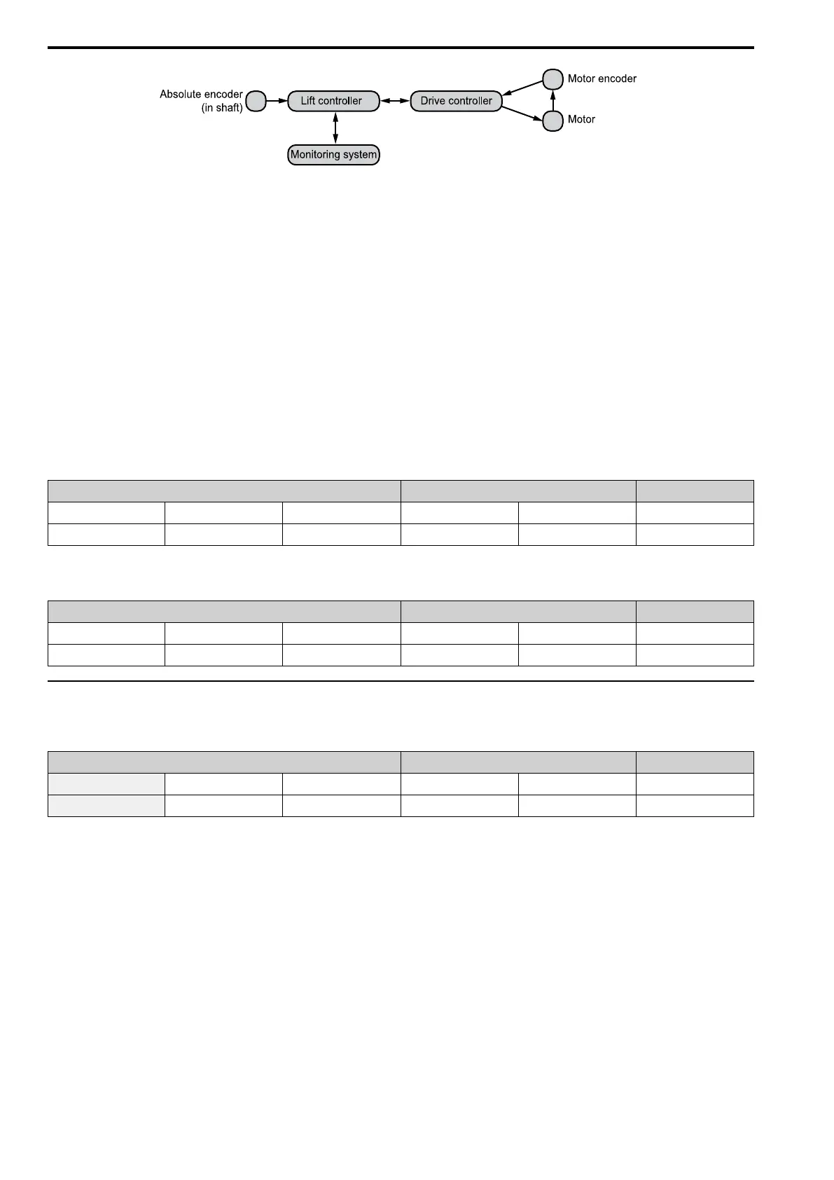
Figure 6.2 Typical DCP Topology
Drive and lift controller are linked via RS-485 using the fixed communication settings:
• Baud rate: 38,400 Baud
• Parity: none
• Data bits: 8
• Stop bits: 1
■ Messages
• Time-critical, high speed process data (e.g. remaining distance, switch-off points, travel commands, etc)
• Non time-critical communication data (e.g. display control, transfer of keypad codes, etc.)
• Not more than 2 bytes of communication data are transferred with each message; the remaining bytes being
used for fast process data.
• Each message is provided with a checksum byte
Master Messages from Lift Controller to Drive Controller
Fixed length of 6 bytes
Process Data Communication Data Checksum
1 2 3 4 5 6
Command Byte Data Byte 1 Data Byte 2 Communication Byte 1 Communication Byte 2 Checksum
Slave Messages from Drive Controller to Lift Controller
Fixed length of 6 bytes
Process Data Communication Data Checksum
1 2 3 4 5 6
Status Byte Data Byte 1 Data Byte 2 Communication Byte 1 Communication Byte 2 Checksum
◆ DCP Master Messages from Lift Controller to Drive Controller
■ Command Byte
Process Data Communication Data Checksum
1 2 3 4 5 6
Command Byte Data Byte 1 Data Byte 2 Communication Byte 1 Communication Byte 2 Checksum
The first byte of the message is called command byte. It contains the following information:
Bit B0 : Drive controller enable
DCP3 and DCP4:
Information for the drive that there will be activation soon. This bit is set during a travel.
0 : No activation of the drive (e.g. finish of travel or travel interruption)
1 : Drive activation during travel
Bit B1 : Travel command (DCP3); Change of actual distance (DCP4)
DCP3:
The speed is set with the travel command.
This bit is cleared at the deceleration point and the drive slows down to V0 (Crawl speed).
DCP4:
Remaining Distance Travel: With a travel dependent on distance, bit B1 is cleared since the drive controller itself
determines the optimum switch-off point. The speed transferred before the start of the travel is just a limit.

 Loading...


