6 DCP Interface
YASKAWA TOEPC710616134G AC Drive L1000A Technical Manual Addendum 17
An incorrect setting may result in poor performance or nuisance faults or alarms.
6 DCP Interface
The DCP is a point-to-point link between drive controller and lift controller. The two devices are linked via an
RS-485 interface in semi-duplex mode.
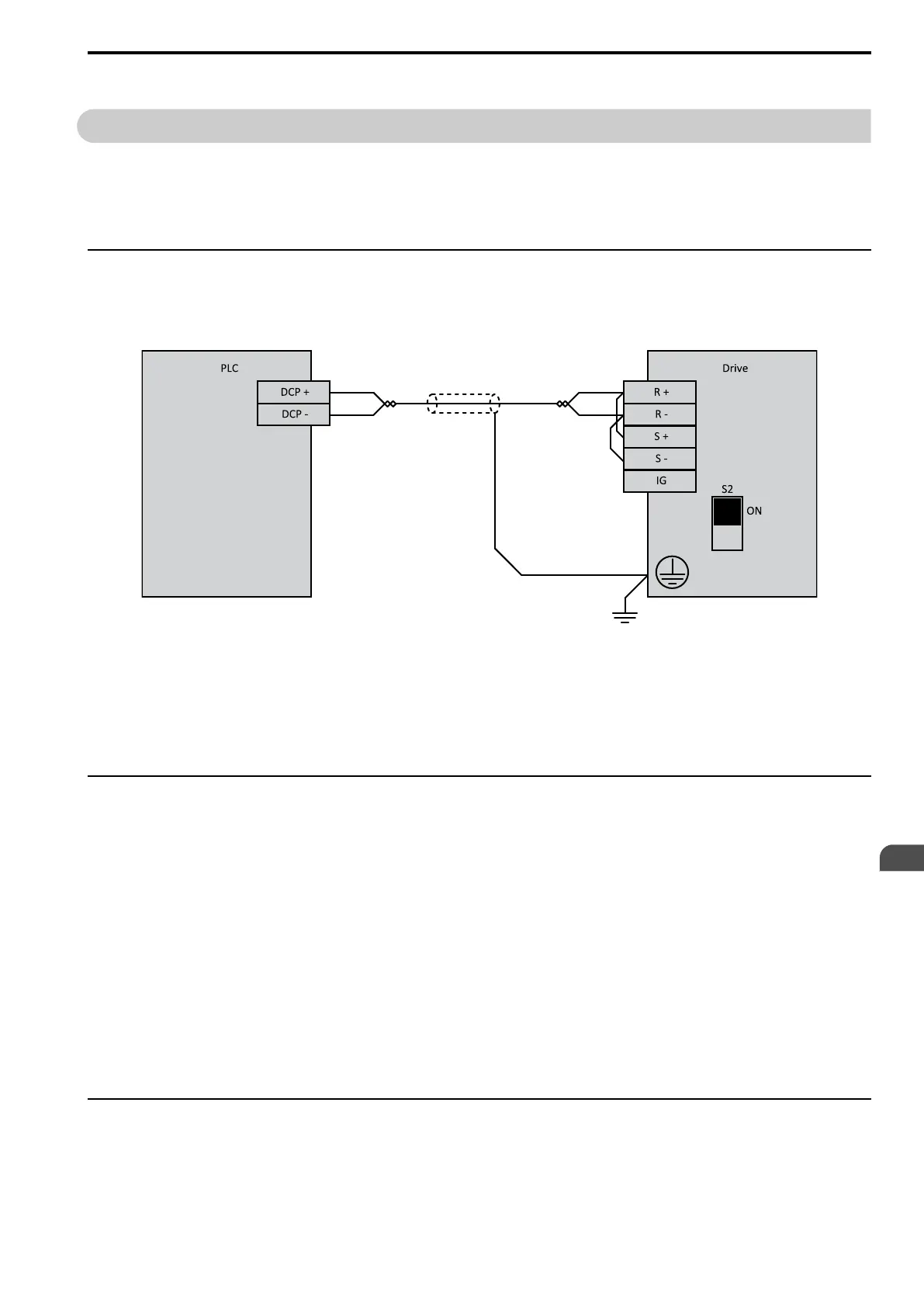
For DCP serial communications, the terminal connections for RS485 R+/R-/S+/S- have to be used (R+ and S+ /
R- and S- bridged).
◆ Network Cable Connection
• With the power shut off, connect the communications cable to the drive and the master. Use terminals R+/S+
and R-/S- for DCP.
• Set DIP switch S2 to ON position.
Figure 6.1 RS-485 DCP Connection
Note:
1. Turn on the DIP switch on the drive that is located at the end of the network. All other slave devices must have this DIP switch set to
OFF position.
2. Set H5-07 = 1 when using the RS-485 interface.
3. Cycle power to apply the H5-07 change.
◆ Introduction
The DCP protocol distinguishes two modes:
DCP3 (for lift controllers without absolute encoder system in the shaft) :
• Drive control via serial DCP link instead of digital inputs
• Status messages, such as fault and over-temperature, are transmitted via DCP link instead of by relay
• Monitoring of speed (such as releveling speed, deceleration speed, and overspeed)
DCP4 (for lift controllers with absolute encoder system in the shaft) :
• Drive control via serial DCP link instead of digital inputs
• Status messages, such as fault and over-temperature, are transmitted via DCP link instead of by relay
• Monitoring of speed (such as releveling speed, deceleration speed, and overspeed)
• Time-optimized direct leveling dependent on remaining distance
• Millimeter-accurate adjustment, dependent on distance
• Supervision of deceleration at the shaft ends
◆ Characteristics of DCP Interface
In DCP mode a Master-Slave-architecture is used. The lift controller is the master device, the drive controller is
the slave. Messages for communication between the devices are sent in a 15 ms cycle.
EN

 Loading...


