6 DCP Interface
34 YASKAWA TOEPC710616134G AC Drive L1000A Technical Manual Addendum
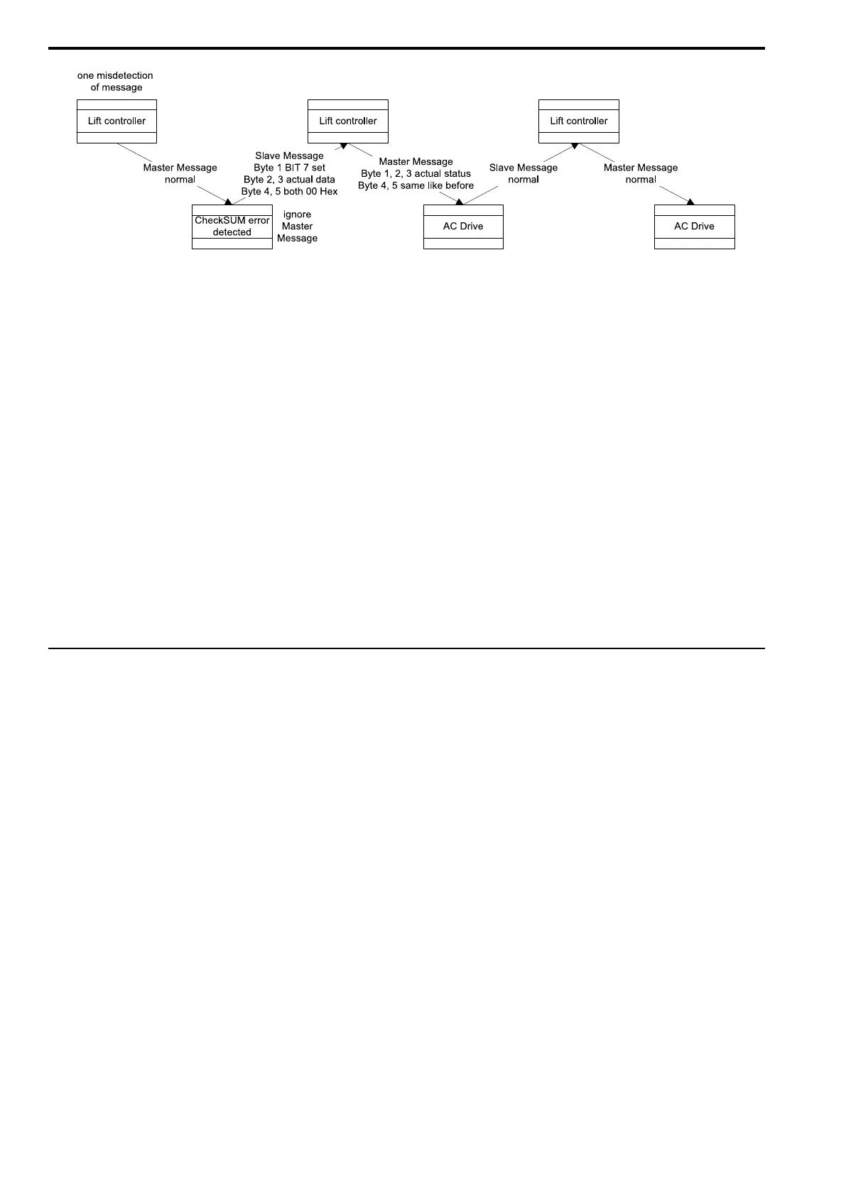
Bit 7 of byte 1 in master and slave message can initiate a resending of the previous message. In both cases, it is
necessary to respond as follows: The type of message must be maintained (i.e. bytes 4 and 5 are the same as in the
previous message). The actual values are transferred as commands.
■ Drive Controller
A :
The drive controller has detected a checksum error in the message received from the lift controller. The drive
controller ignores the message and sends a reply message with the following content:
• Status Byte: Contains the actual status of the drive controller with bit 7 set (error in the last message received)
• Process Data: Contains the actual extended status or the actual deceleration distance (which is 00 (Hex)in DCP3
mode)
B :
In the message from the lift controller to the drive controller, bit 7 (error in last reply message) is set in the
command byte. The current commands are processed normally. The drive controller repeats the last message sent.
Note:
If one of both devices is detecting a checksum error in a message when also bit 7 (error in last message) is set, this bit must be ignored
by the receiving device. In DCP4 mode, the drive controller's use of remaining distance message simplifies the behavior:
• The lift controller always sends the current command byte and the remaining distance
• The drive controller always replies with the current status byte
• In the event of transmission errors, only the last communication byte sent is repeated
◆ Basic DCP Serial Communication Parameters
■ Interface
RS485 is used as physical layer. Transmission from the lift controller to the drive controller is serial and
asynchronous.
• Baud rate: 38,400 Baud
• Data bits: 8
• Parity: none
• Stop bits: 1
■ Timing
Since a half-duplex interface is used, the corresponding line drivers must be switched on or off dependent on the
transmission direction. To avoid collisions, the following timing has to be followed:
• Maximum Tx transmission driver switch-off time: 0.5 ms after the last bit was sent
• Maximum time delay for responding to a lift controller message: 10 ms after the last bit was received
• Lift controller message transmission start: 0 ms
• Latest time for switching off lift controller's Tx driver / Earliest time for drive controller transmission start:
2.0624 ms
• Latest drive controller transmission start: 11.5625 ms
• Latest time for switching off drive controller Tx driver / Earliest start for sending next lift controller message:
13.625 ms
• This leads to a transfer cycle of: 15 ms

 Loading...


