6 DCP Interface
44 YASKAWA TOEPC710616134G AC Drive L1000A Technical Manual Addendum
There are two ways to control a drive using DCP4:
1. DCP4 mode with transfer of desired travel distance and braking distance before start
Before starting, there is a data exchange between controller and drive using message 'I','7'. The drive does not
have to be able to transmit the braking distance while driving.
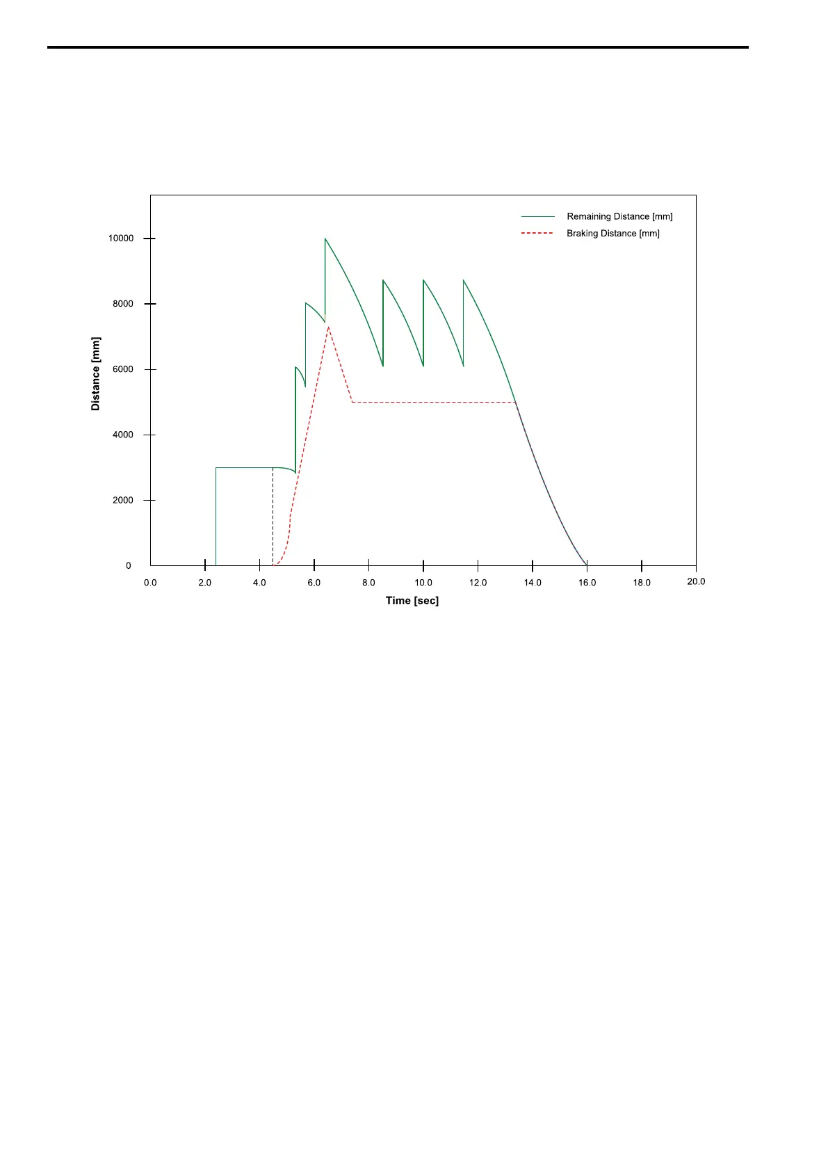
2. DCP4 mode with transfer of current braking distance while driving
Before starting, there is no data exchange by using message 'I','7' telegram. While traveling, the drive
permanently sends the actual braking distance.
Figure 6.12 Travel with Remaining Distance and Actual Braking Distance (DCP4)
■ Time-Optimized Direct Leveling Dependent on Remaining Distance
With time-optimized travels dependent on remaining distance, there are no points at which lift speeds are
switched. Dependent on the distance to be traveled, the corresponding maximum speed V5, V3, or VN might not
be reached during the travel. Instead, the optimum speed for reaching the destination is determined. The lift
travels to the destination at this speed. To clearly distinguish them from DCP3 travels, the DCP4 mode travels are
therefore identified with an apostrophe (').
The travels described below have the following common features:
• Before the travel starts, a preselected speed is transmitted. This is just a limit that the drive controller is not
allowed to exceed. The actual value of the speed is decided by the drive controller itself by calculating the time-
optimized travel curve based on the actual remaining distance.
• The travels dependent on remaining distance are executed without travel command bit B1.
• Right from the travel start, the absolute remaining distance is read via DCP.
• Stop switch bit B2 remains active until the lift car reaches the level and the drive controller switches the
mechanical brake bit S6 off.
V4' Travel :
1. Before the travel starts, the speed mode "Fast [bit G7]" (V4) is transmitted.
2. The travel starts with activation of the stop switch bit B2. After starting the travel, the absolute remaining
distance can be read via DCP.
3. The drive decelerates until the lift car comes to the level without driving crawl speed. The drive controller
then switches the mechanical brake bit S6 off.
4. The controller does not withdraw the stop switch bit B2 until mechanical brake bit S6 is switched off. The
maximum deceleration distance is SV4'.

 Loading...


