6 DCP Interface
YASKAWA TOEPC710616134G AC Drive L1000A Technical Manual Addendum 61
Monitor Operator Display Description
Analog Output
Scaling (H4-xx
selection)
Unit
U4-85 I0 Cmd Rcv Ctr
I0 Command Reception Counter
Counts the valid ‘I0’ commands received by the drive. The counter will roll
after 65535 counts.
- 0 - 65535
U4-86 I1 Cmd Rcv Ctr
I1 Command Reception Counter
Counts the valid ‘I1’ commands received by the drive. The counter will roll
after 65535 counts.
- 0 - 65535
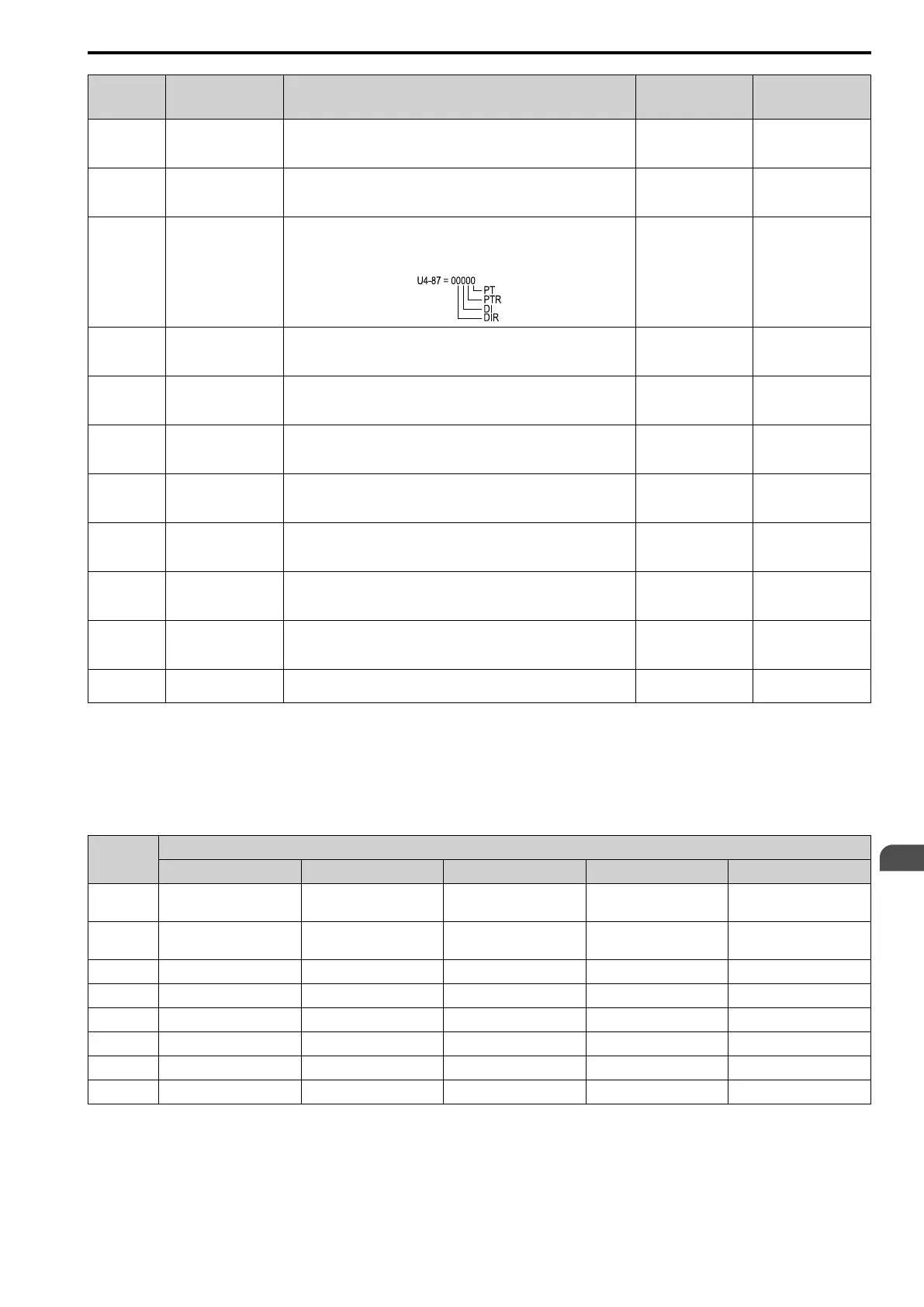
U4-87 I1 DIR DI PTR PT
I1 Command Request and Reply
Shows Data Information Type Request (DIR) from controller, Data
Information Type (DI) acknowledged by drive, Protocol Type Request (PTR)
from controller, and acknowledged Protocol Type (PT)
- -
U4-88 I6 Cmd Rcv Ctr
I6 Command Reception Counter
Counts the valid ‘I6’ commands received by the drive. The counter will roll
after 65535 counts.
- 0 - 65535
U4-89 I7 Cmd Rcv Ctr
I7 Command Reception Counter
Counts the valid ‘I7’ commands received by the drive. The counter will roll
after 65535 counts.
- 0 - 65535
U4-90 I7 Rx Data V4
I7 Reception Data when V4 Commanded
Shows the distance command transferred in an ‘I7’ message (controller to
drive) with V4 speed selection.
-
0.001 m
(0.01 in)
*1
U4-91 I7 Rx Data V3
I7 Reception Data when V3 Commanded
Shows the distance command transferred in an ‘I7’ message (controller to
drive) with V3 speed selection.
-
0.001 m
(0.01 in)
*1
U4-92 I7 Tx Data Sg
I7 Transmit Data Sg
Shows the total distance to be traveled according to the transferred distance
command.
-
0.001 m
(0.01 in)
*1
U4-93 I7 Tx Data Sv
I7 Transmit Data Sv
Shows the deceleration distance according to the transferred distance
command.
-
0.001 m
(0.01 in)
*1
U4-94 I9 Cmd Rcv Ctr
I9 Command Reception Counter
Counts the valid ‘I9’ commands received by the drive. The counter will roll
after 65535 counts.
- 0 - 65535
U4-95 I7 Profile Type
Shows the ‘I7’ communicated profile type as it was determined by the drive
according to the last query by the controller.
- -
*1 Values not in parentheses apply when o1-12 = 0. Values in parentheses apply when o1-12 = 1.
■ Added Standard Parameter Dependencies
The baud rate for DCP operation is specified as 38,400 baud. When DCP operation is selected by H5-13, the baud
rate of the Memobus port, accessible via terminals R+, R-, S+, S-, is automatically set to 38,400 baud. The values
of the following parameters are changed automatically according to the settings of H5-13.
Dependent
Parameter
H5-13 = x
0 [DCP Com Channel] 1 [Memobus/Modbus] 3 [DCP3] 4 [DCP4] 5 [CANopen-Lift]
b1-01
(sequence)
6 [DCP] 0 [Operator Keypad] 6 [DCP] 6 [DCP] 6 [DCP]
b1-01
(reference)
6 [DCP] 1 [Control Circuit Terminal] 6 [DCP] 6 [DCP] 6 [DCP]
F6-35 0 [Node ID] 0 [Node ID] 0 [Node ID] 0 [Node ID] 2 [Node ID]
F6-36 6 [500 kBaud] 6 [500 kBaud] 6 [500 kBaud] 6 [500 kBaud] 5 [250 kBaud]
H3-02 0 [Frequency Bias] 0 [Frequency Bias] 1F [not used] 1F [not used] 1F [not used]
H5-02 5 [38400 Baud] 3 [9600 Baud] 5 [38400 Baud] 5 [38400 Baud] 3 [9600 Baud]
H5-11 1 [Enter Cmd not necessary] 0 [Enter Command necessary] 1 [Enter Cmd not necessary] 1 [Enter Cmd not necessary] 1 [Enter Cmd not necessary]
S4-01 3 [Advanced] 0 [Disabled] 3 [Advanced] 3 [Advanced] 0 [Disabled]
Note:
1. Parameter values are set to default when H5-13 is changed.
2. Do a power cycle after you switched H5-13 ≠ 1 or after you switched back to H5-13 = 1 to let the new H5-02 setting take effect.
3. When H5-13 = 4, S4-01 is not shown.
EN

 Loading...


