6 DCP Interface
YASKAWA TOEPC710616134G AC Drive L1000A Technical Manual Addendum 19
Desired Distance Travel: Not implemented.
Bit B2 : Stop switch
DCP3:
The stop switch replaces terminal input V0 (Crawl speed).
DCP4:
In this mode, the lift controller signals that the drive controller performs a distance-dependent travel. The stop
switch is turned on from the start of the travel.
When the drive controller reaches the remaining distance of 0 mm, the mechanical brake is applied. The lift
controller then turns off the stop switch.
Bit B3 : Transfer of travel commands in the third byte of message
DCP3 and DCP4:
This bit tells the drive controller that the following 2 bytes (data bytes) are being used to transfer a speed.
Bit B4 : Direction of travel
DCP3 and DCP4:
This bit determines the direction of travel of the lift.
0 : Upwards
1 : Downwards
Bit B5 : Speed change
DCP3 and DCP4:
This bit has the same functionality as B3 (implemented as logical OR combination).
Bit B6 : Desired distance / Actual distance
DCP4:
This bit chooses the type of transmitted distance.
0 : Actual Distance
1 : Desired Distance (not supported)
Bit B7 : Error in last reply message
DCP3 and DCP4:
This bit is set when the lift controller has detected a checksum error in the last message received from the drive
controller and has therefore ignored it. In this case, the drive controller repeats the telegram automatically.
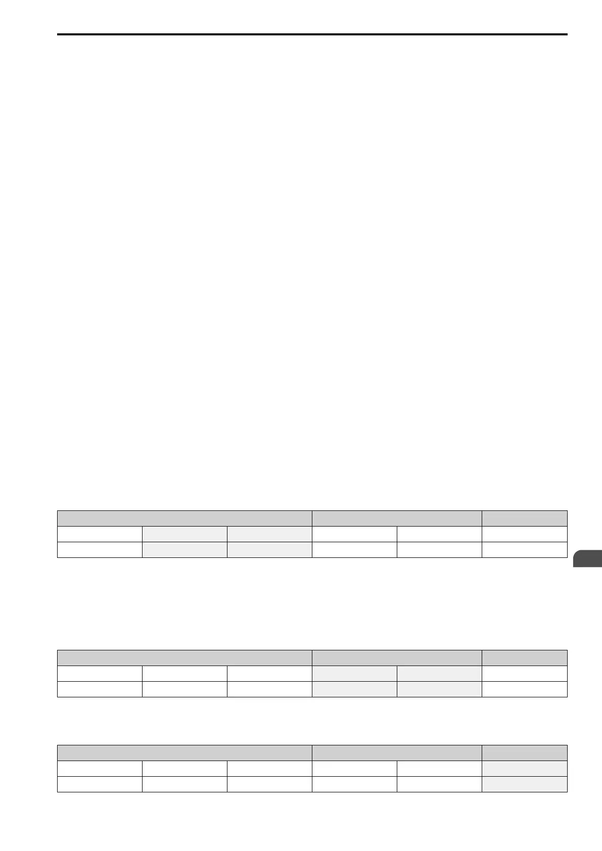
■ Data Bytes
Process Data Communication Data Checksum
1 2 3 4 5 6
Command Byte Data Byte 1 Data Byte 2 Communication Byte 1 Communication Byte 2 Checksum
The content of the two data bytes depends on the type of transmitted message. Transmitted information:
• Speed Mode
• 15-bit remaining distance
• 16-bit remaining distance
■ Communication Bytes
Process Data Communication Data Checksum
1 2 3 4 5 6
Command Byte Data Byte 1 Data Byte 2 Communication Byte 1 Communication Byte 2 Checksum
The exact meaning and function of the communication bytes are described later.
■ Checksum Byte
Process Data Communication Data Checksum
1 2 3 4 5 6
Command Byte Data Byte 1 Data Byte 2 Communication Byte 1 Communication Byte 2 Checksum
EN

 Loading...


