10 Input Phase Loss Detection
80 YASKAWA TOEPC710616134G AC Drive L1000A Technical Manual Addendum
◆ Power-On dv/dt Threshold Tuning
When you set L8-79 ≥ 100%, the drive determines the value for L8-70 [dv/dt Threshold] during the first start after
power-on. The drive will save the value after the travel has ended. During this first start, the dv/dt method Input
Phase Loss Detection is disabled.
When you change L8-79 [dv/dt Tuning Factor] and confirm with Enter, the drive will determine the new value for
L8-70 during the next travel. The drive will save the value after the travel has ended.
The maximum dv/dt value during S1-06 [Brake Release Delay Time] is determined and saved. The drive
calculates the new dv/dt value as S1-06 × L8-79. This value is only stored when it differs ±50 V/s from the
existing setting of L8-70. When you set L8-79 = 99%, this tuning function is disabled, and L8-70 will not be
modified.
◆ Input Phase Loss Detection Method Selection
Use L8-05 [Inp Ph Loss Det] to activate the Input Phase Loss Detection function.
Parameter
(Hex.)
Operator Display Description Value Range Default Value
L8-05
(04B1)
Inp Ph Loss Det
Input Phase Loss Detection Method
Enables or disables the input phase loss detection.
0 : Disabled
Lift controller decides the direction with S1/S2
2 : Enabled during operation
6 : Standard + dv/dt
dv/dt @Start and Standard detection during RUN
0, 2, 6 2
◆ Further Modifications
■ Output Phase Loss Detection (OPLD)
OPLD During RUN :
The output phase loss detection function is modified to ensure that no false detections occur during RUN when
the lift car is balanced.
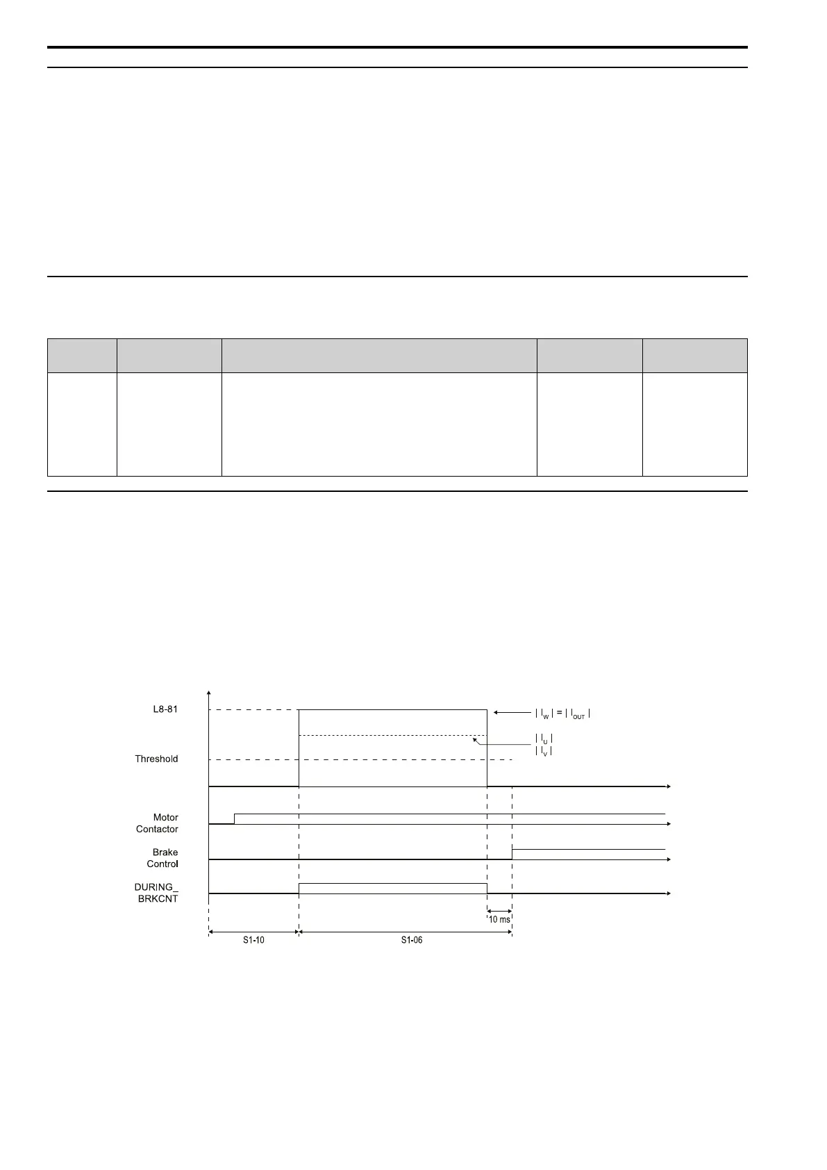
OPLD at Start :
Parameter L8-81 sets the injection current for PM motors in % dependent on the selected motor rated current. The
threshold value for the phase loss detection is calculated and set to half of |IU| = |IV| value. If one of the phase
currents falls below this threshold for more than 100 ms, LF fault is triggered.
Figure 10.3 Output Phase Loss Detection Parameters and Timing During Injection

 Loading...


