2 Brake Monitoring (Unintended Car Movement)
8 YASKAWA TOEPC710616134G AC Drive L1000A Technical Manual Addendum
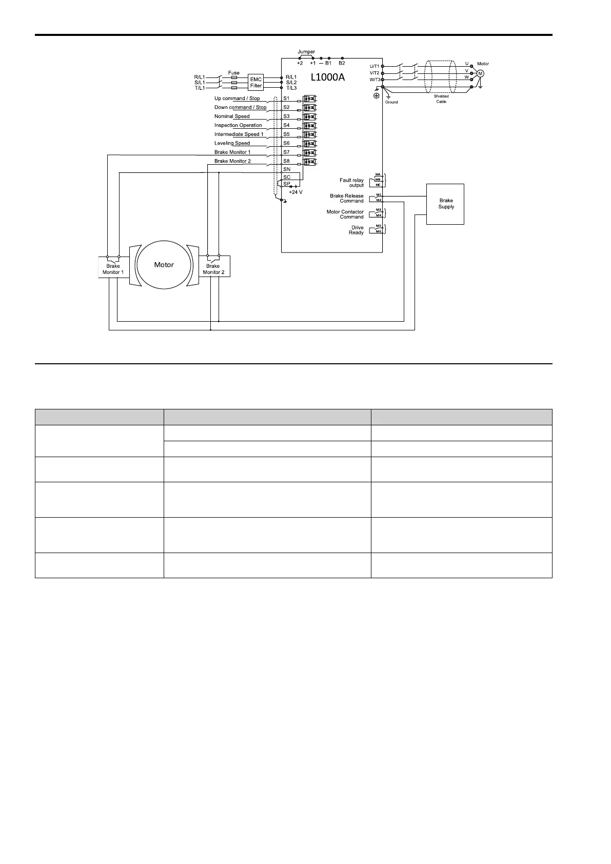
Figure 2.1 Wiring Example: How to Wire the Drive and Motor Brakes
◆ Activation/Deactivation
The following table provides an overview of the parameters necessary for the Brake Response Monitor.
Parameter Number Parameter Name Setting Range
H1-xx
Brake Feedback 1 79h (N.O.)
Brake Feedback 2 5Bh (N.C.)
S6-17 Brake Response Monitor
0 = Deactivated (Default)
1 = BRM Function Active
S6-05 Brake Response Error (SE4) Detection Time
Default 500 ms
Min. 100 ms
Max. 10,000 ms
S6-06 Brake Response Error (SE4) Detection Time During Run
Default 500 ms
Min. 100 ms
Max. 60,000 ms
S6-18 SE4 Fault Reset
0 = No reset (Default)
1 = Reset SE4 Fault
The Brake Response Error Detection Time is adjustable in parameter S6-05. Default detection time is 500 ms.
The Brake Response Error Detection Time During Run is adjustable in parameter S6-06. Default detection time is
500 ms.
■ Activation
The Brake Response Monitor (BRM) function is not active by default. The Brake Feedback function must be
programmed to two digital inputs of the drive.
To activate the BRM function, perform the following steps:
• Set S6-17 = 1.
• Program the Brake Feedback function to two digital inputs of the drive.
For example:
– Input S7 -> H1-07 = 79h
– Input S8 -> H1-08 = 79h
If S6-17 = 0, but Brake Feedback 1 and Brake Feedback 2 are wired and Brake Control [H2-xx = 50h] is used, the
L1000A standard Brake Feedback Function is active, but the mode of operation is not A3-compliant. This Brake

 Loading...


