6 DCP Interface
YASKAWA TOEPC710616134G AC Drive L1000A Technical Manual Addendum 21
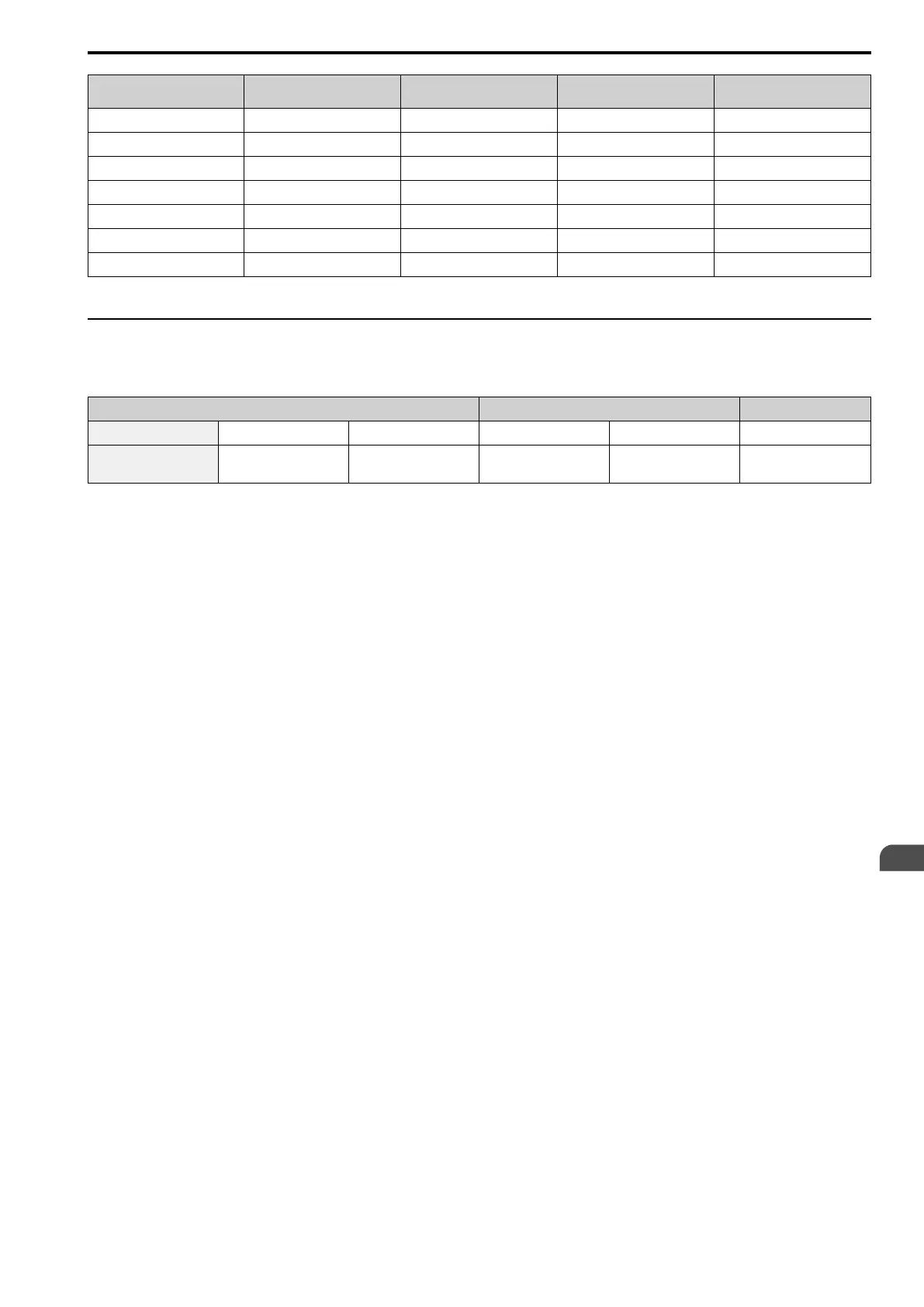
Speed Mode Bits DCP Name of Speed Mode
L1000A Standard Speed
Designation
Related L1000A Parameter L1000A DCP Designation
G4 VI Inspection d1-24 VI Speed
G5 V2 Intermediate 2 d1-03 V2 Speed
G6 V3 Intermediate 1 d1-02 V3 Speed
G7 V4 Fast d1-01 V4 Speed
G8 V5 Intermediate 6 d1-07 V5 Speed
G9 V6 Intermediate 5 d1-06 V6 Speed
G10 V7 Intermediate 4 d1-05 V7 Speed
Speed modes V7, V6, V5, V2, and V1 are not available with DCP4.
◆ DCP Slave Messages from Drive Controller to Lift Controller
■ Status Byte
Process Data Communication Data Checksum
1 2 3 4 5 6
Status Byte
(S7 ... S0)
Data Byte 1 Data Byte 2 Communication Byte 1 Communication Byte 2 Checksum
The first byte of the message is called status byte. It contains the following information:
Bit S0 : Drive controller ready
DCP3 and DCP4:
The drive controller is ready for the next run. This status bit is similar to the terminal "Drive controller ready" at
the lift controller.
0 : Drive controller is not ready to travel
1 : Drive controller is ready to travel
Bit S1 : Travel active
DCP3 and DCP4:
The drive controller is currently carrying out a run.
0 : Not in travel
1 : In travel
Bit S2 : Stop switch
DCP3 and DCP4:
The travel can be continued to the next floor. In this case, the lift controller should no longer give any travel
commands while alarms are active.
Bit S3 : Fault active
DCP3 and DCP4:
The drive controller error flag is set. The drive controller has been switched off, the run contactor was closed, and
the brake was applied. Possible causes of the fault include:
• Over-speed
• Over-current
• DC bus over-voltage
• DC bus under-voltage
• Motor parameter setting error
• Power section over-temperature
The command "Drive controller enable" (see command bit B0) must be cleared at this situation. The lift controller
will not travel until the fault has been cleared on the drive side.
Bit S4 : Motor speed below leveling speed (v < 0.3 m/s)
DCP3 and DCP4:
The motor speed has dropped to or below leveling speed. This signal is used for monitoring the re-leveling speed
(v < 0.3 m/s) by the lift controller.
EN

 Loading...


