3.7Forming a Protective Sequence
131
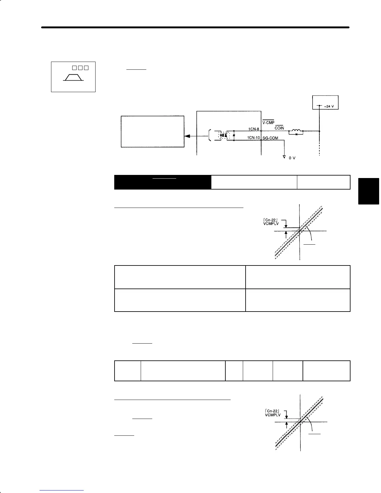
3.7.4 Using Speed Coincidence Output Signal
1) This section describes how to wire and use contact output signal “speed coincidence out-
put (V-CMP
).” This signal is output to indicate that actual motor speed matches a refer-
ence speed. The host controller uses this signal as an interlock.
Photocoupler Output
Per output:
Maximum operation
voltage: 30 VDC
Maximum output
current: 50 mADC
Servopack
I/O power
supply
Output → V-CMP 1CN-8
Speed Coincidence Output For Speed/Torque
Control Only
For speed/torque control (SGDA-
jjj
S) only.
This output signal indicates that actual motor
speed matches the input speed reference during
speed control.
ON
status:
Circuit between 1CN-8 and 1CN-10 is
closed.
1CN-8 is at low level.
Actual motor speed matches the speed
reference (speed difference is below the
preset value).
OFF
status:
Circuit between 1CN-8 and 1CN-10 is
open.
1CN-8 is at high level.
Actual motor speed does not match the
speed reference (speed difference is
greater than the preset value).
Preset value: Cn-22 (speed coincidence signal output width)
2) Set the following user constant to specify the output conditions for speed coincidence
signal V-CMP
.
Cn-22
VCMPLV Speed Coincidence
Signal Output Width
Unit:
r/min
Setting
Range: 0
to 100
Factory
Setting:
10
For
Speed/Torque
Control Only
For speed/torque control (SGDA-
jjj
S).
Set the output conditions for speed coincidence
signal V-CMP
(1CN-8).
V-CMP
signal is output when the difference be-
tween the reference speed and actual motor
speed is not greater than the preset value.
3
SGDA- S
Speed/Torque
Motor
speed
Reference
speed
V-CMP is output within
this range.
Motor
speed
Reference
speed
V-CMP
is output
within this range
 Loading...


