INSPECTION, MAINTENANCE AND TROUBLESHOOTING
6.2.3 Internal Connection Diagram and Instrument Connection Examples
368
6.2.3 Internal Connection Diagram and Instrument Connection
Examples
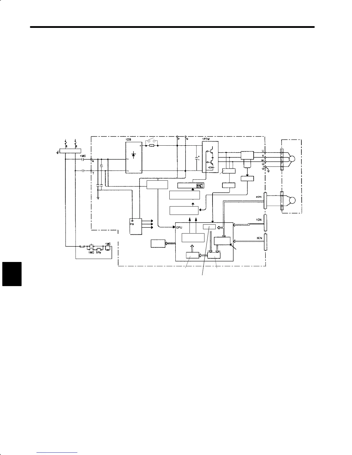
The SGDA Servopack internal connection diagram and instrument connection examples are
given below.
Refer to these diagrams during inspection and maintenance.
1) Internal Connection Diagram (for speed/torque control and position control)
Single-phase 200 to 230 VAC 50/60 Hz
or single-phase 100 to 115 VAC 50/60 Hz
Noise Filter
Main
Circuit
OFF
Main
Circuit
ON
Surge
Suppressor
Control
Power
Supply
Alarm
Display
Fault
Detection
Isolator
PWM Generator
Circuit
Power Supply
Control Circuit
Current
Reference
Current Control
Position
Control
Speed Control
For Position
Control Only
DB Circuit
Relay
Current
Detector
Current
Detection
Servomotor
Red
White
Blue
Green
Encoder
For I/O Signals
For Digital Operator
+ 10
–15
%,
+ 10
–15
%,
-5V
PG5V
Speed Calculation
+5V
6
 Loading...


