6.2Troubleshooting
369
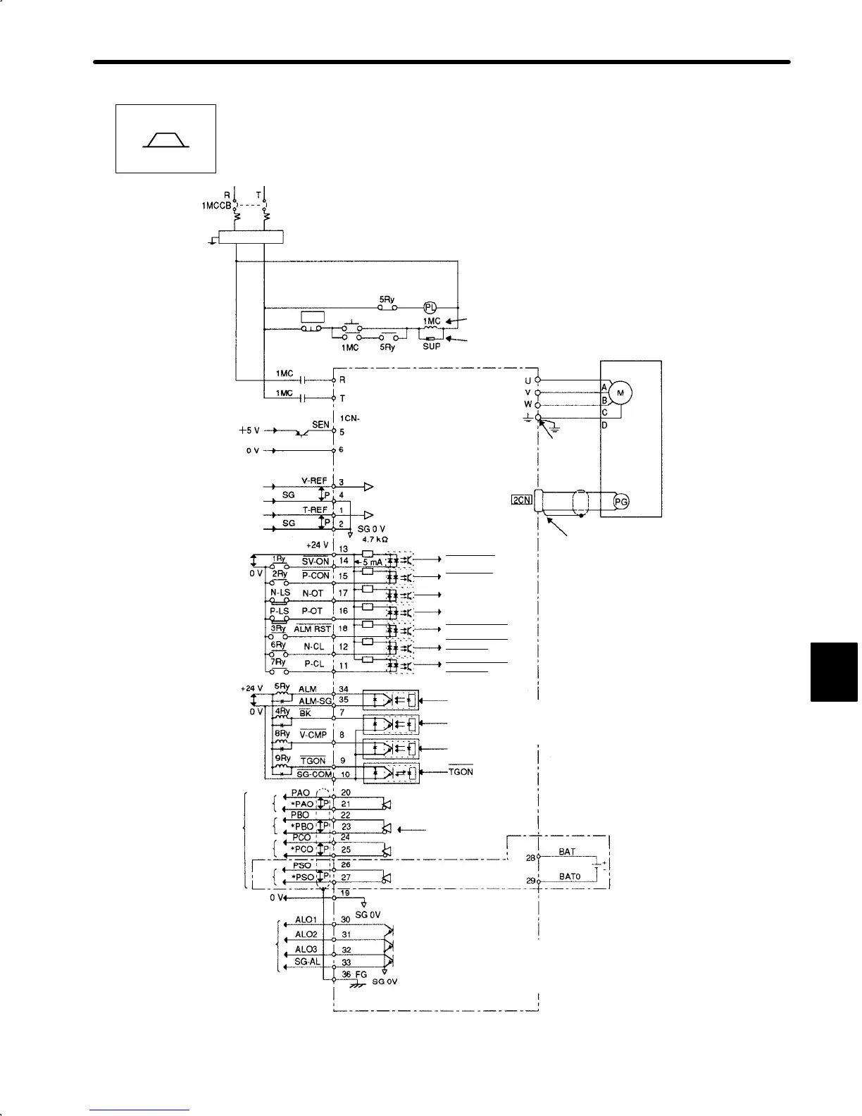
2) Instrument Connection Examples − Speed/Torque Control
For 100 V Application
Single-phase 100 to 115 VAC 50/60 Hz
Noise Filter Noise filter eliminates external noise.
Power
Supply
ON
OFF
Servo Alarm Display
For Power Supply Switching
Attach surge suppressor to
magnetic contactor and relays.
Servopack
(SGDA-jjjS)
Servomotor
Must be
grounded
Class 3
grounding
(100 Ω max.)
Encoder
Correctly terminate
end of shielded cable.
SEN Signal Input
Speed Reference Input
Rated Speed / ±2Vto±10 V
Torque Reference Input
Rated Torque / ±2Vto±10 V
Servo ON for 1Ry ON
P Control for 2Ry ON
Reverse Drive Disabled for N-LS OPEN
Forward Drive Disabled for P-LS OPEN
Alarm Reset for 3Ry ON
Reverse Current Control ON for 6Ry ON
Forward Current Control ON for 7Ry is ON
5Ry OFF for Servo Alarm
4Ry OFF for External Motor Brake ON OK
8Ry ON for Speed Match ON.
9Ry ON for TGON
PG Output
Line Driver
Alarm Code Output
Phase
A
Phase
B
Phase
C
Phase
S
Servo ON
P
Control
Reverse Drive Disabled
Forward Drive Disabled
Alarm Reset
Reverse Current
Control ON
Forward Current
Control ON
Servo Alarm
Photocoupler Output
Maximum operational voltage: 30 VDC
Maximum operational current: 50 mA
Brake
Interlock
Speed
concidence
Turned ON when the
motor zero-speed
level (set in the pa-
rameter) is exceeded
For Absolute
Encoder
Line Driver
SN75ALS194NS
(manufactured by T-I)
Note 1: The capacity of each output circuit is below 30 VDC and 50 mA.
2: Signal input line
↕
P represents twisted pair wires.
3: I/O power supply must be prepared by customers.
Single-phase 200 to 230 VAC 50/60 Hz
+ 10
–15
%
+ 10
–15
%
6
SGDA-jjjS
Speed/Torque
 Loading...


