3.7 Forming a Protective Sequence
131
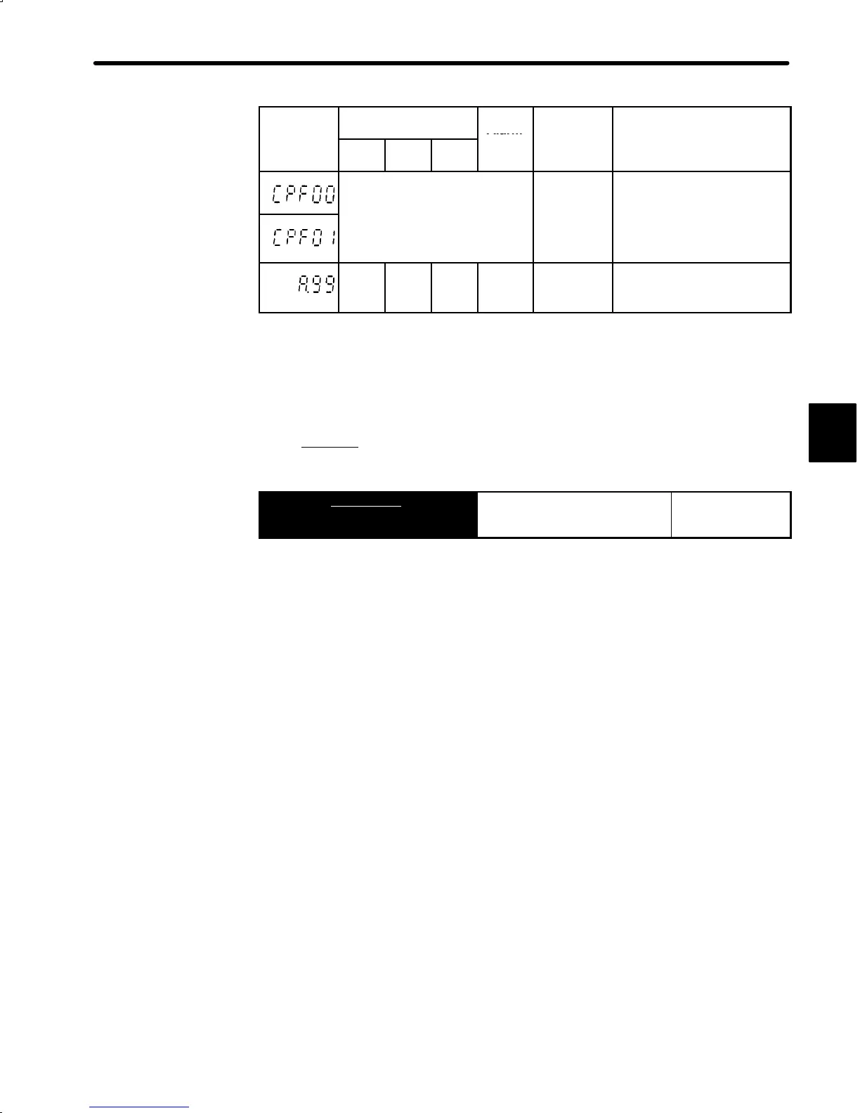
Alarm
Alarm Code Output
Servo
Alarm
Display
ALO1 ALO2 ALO3
(ALM+)
Output
arm
ype
arm
escr
pt
on
Digital
Operator
transmis-
Communication error oc-
curred between Digital Oper-
ator and Servo
ack.
Undefined
sion error
.
¢
¢ ¢
○
No error
○ : Output transistor is ON
¢ : Output transistor is OFF
* : Displays an alarm category number.
For details, refer to Appendix E List of Alarm Displays.
5) When the servo alarm (ALM+) is output, eliminate the cause of the alarm and set the fol-
lowing ALMRST
input signal at low level (0V) to reset the alarm state.
→ Input ALMRST 1CN-44
Alarm Reset For Speed/Torque
Control and
Position Control
This signal is used to reset the servo alarm state.
Alarm state can be reset using the Digital Operator.
Also, alarm state is reset at control power ON/OFF.
When an alarm occurs, always eliminate the cause before resetting the alarm
state. 6.2.1 Troubleshooting Problems with Alarm Display describes how to trou-
bleshoot the system when an alarm arises.
3

 Loading...


