APPLICATIONS OF Σ-SERIES PRODUCTS
3.7.1 Using Servo Alarm Output and Alarm Code Output cont.
130
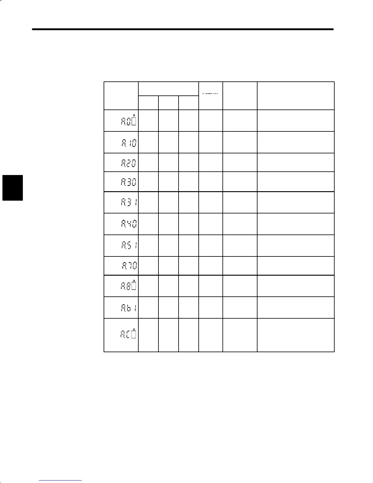
4) Relationship between Alarm Display and Alarm Code Output
Alarm Display and Alarm Code Output:
Alarm
Alarm Code Output
Servo
Alarm
Display
ALO1 ALO2 ALO3
(ALM+)
Output
arm
ype
arm
escr
pt
on
¢
¢ ¢ ¢
User
constant
error
An absolute encoder error oc-
curred or user constant is
faulty.
○
¢ ¢ ¢
Overcurrent Overcurrent flowed thorough
the main circuit.
Servopack overheated.
¢
○
¢ ¢
Fuse blown Fuse of main circuit power
supply is blown.
○ ○
¢ ¢
Regenera-
tive error
Failure of regenerative circuit
○ ○
¢ ¢
Position
error pulse
overflow
The number of pulses in error
counter has exceeded the
preset value.
¢
¢
○
¢
Overvoltage
or undervol-
tage
Main circuit DC voltage is
overvoltage or undervoltage.
○
¢
○
¢
Overspeed Motor speed has exceeded
the 110% of the maximum al-
lowable speed.
○ ○ ○
¢
Overload Motor and Servopack are
overloaded.
¢
¢ ¢ ¢
Absolute
encoder er-
ror
Absolute encoder is faulty.
¢ ¢ ¢ ¢
Reference
input read
error
Failure of analog voltage ref-
erence input read
○
¢
○
¢
Overrun
Disconnec-
tion of PG
signal line
Overrun occurred due to mo-
tor or encoder signal wiring
faults.
Encoder signal line is discon-
nected.
○ : Output transistor is ON
¢ : Output transistor is OFF
* : Displays an alarm category number.
For details, refer to Appendix E List of Alarm Displays.
3

 Loading...


