USING THE DIGITAL OPERATOR
4.1.6 Operation in Monitor Mode cont.
180
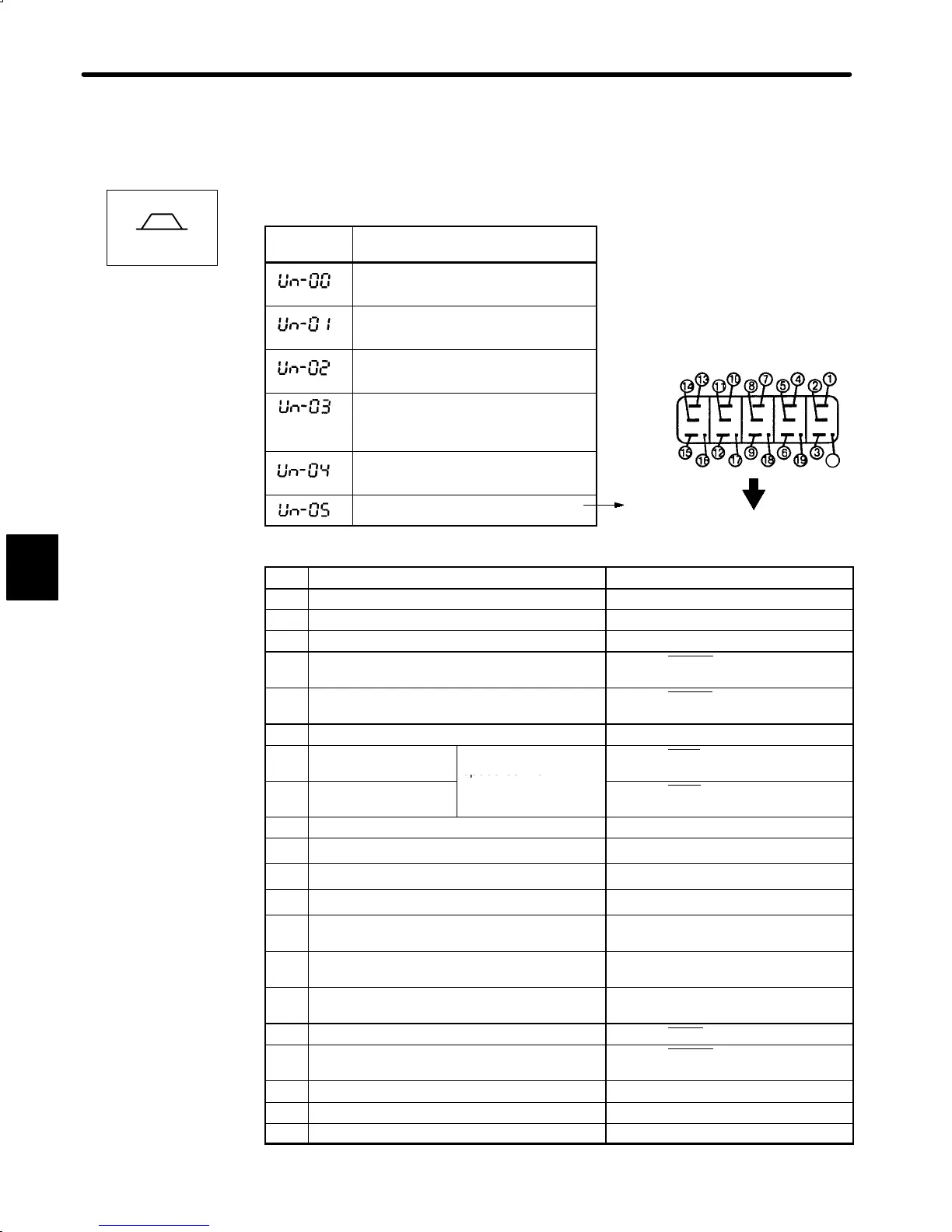
3) Keys to Monitor Mode Display are shown below. Note that the display differs between the
speed/torque control and position control types.
For Speed/Torque Control
Monitor
Number
Monitor Display
Actual motor speed
Units: r/min
Input speed reference
Units: r/min
Internal torque reference Units: %
(with respect to rated torque)
Number of pulses from motor
U-phase edge
Units: pulses
Electrical angle
Units: 0.1deg
Internal status bit display
Bit # Description Related I/O Signal, User Constant
1 Servo alarm 1CN-31(ALM)
2 Dynamic brake ON
3 Reverse rotation mode Cn-02 Bit 0, 2CN-7(DIR)
4 During motor rotation or brake interlock signal 1CN-27 (TG-ON), status display
mode
5 Torque limit or speed coincide 1CN-25 (V-CMP), status display
mode
6 Mode switch ON
7 During forward torque
limit
Or contact input
speed control
1CN-45 (P-CL)
8 During reverse torque
limit
1CN-46 (N-CL)
9 Motor power ON
10 A-phase
2CN-33(PA), 2CN-34(£PA)
11 B-phase
2CN-35(PB), 2CN-36(£PB)
12 C-phase
2CN-19(PC), 2CN-20(£PC)
13 U-phase Only when incremental encoder is
used.
14 V-phase Only when incremental encoder is
used.
15 W-phase Only when incremental encoder is
used.
16 Servo ON 1CN-40 (S-ON) , Cn-01 Bit 0
17 P operation, zero clamp, or rotation direction
input
1CN-41 (P-CON) , Cn-01 Bit A, B,
Cn-02 Bit 2
18 Forward overtravel 1CN-42 (P-OT), Cn-01 Bit 2
19 Reverse overtravel 1CN-43 (N-OT), Cn-01 Bit 3
20 SEN signal input 1CN-4 (SEN)
4
Speed/Torque
Internal Status
Bit Display
see below
20

 Loading...


