4.1 Basic Operations
181
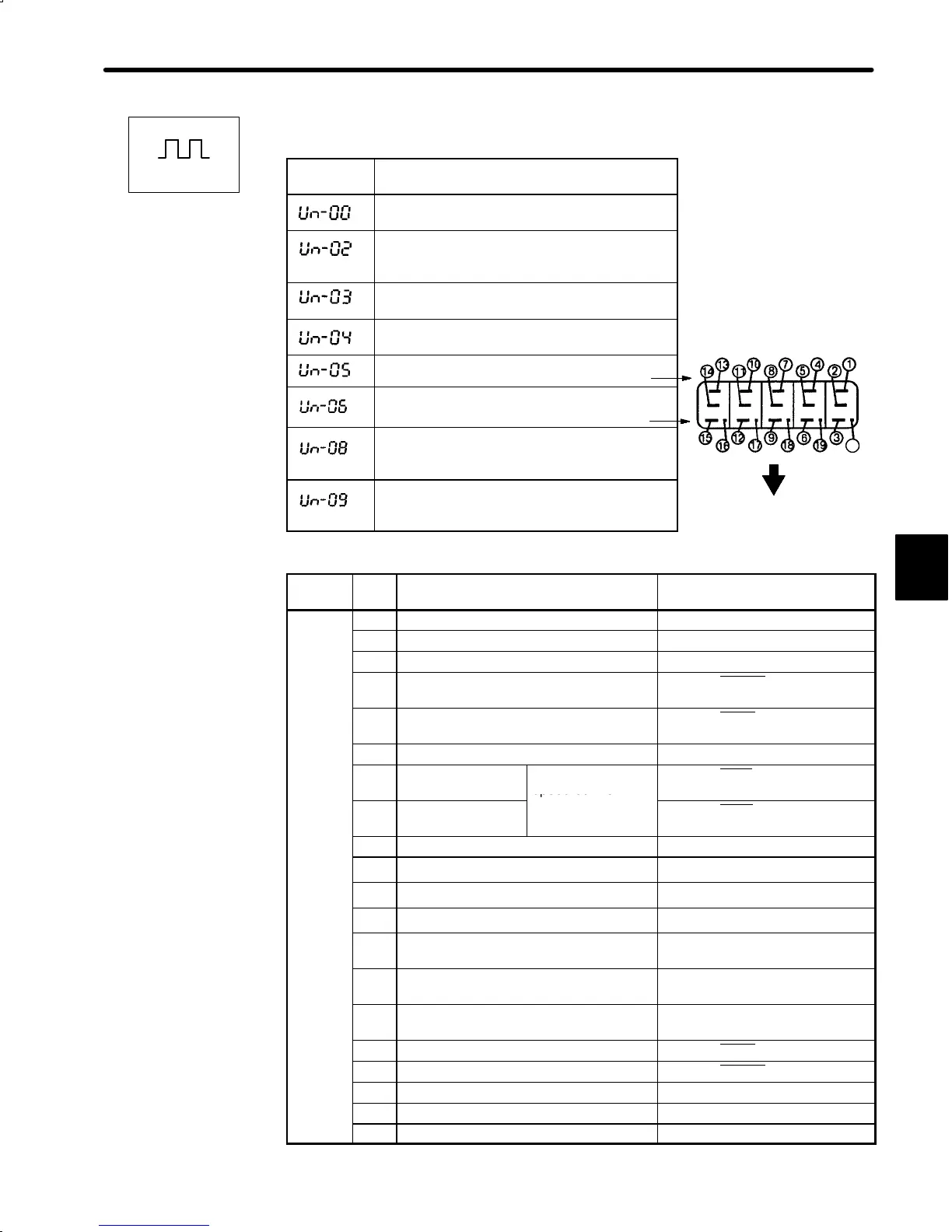
For Position Control
Monitor
Number
Monitor Display
Actual motor speed Units: r/min
Internal torque reference
Units: %
(with respect to rated torque)
Number of pulses from motor U-phase edge
Units: pulses
Electrical angle
Units: 0.1deg
Internal status bit display
Internal status bit display
Positional error
Units: x1 reference unit (Cn-02 Bit E = 0)
x100 reference unit (Cn-02 Bit E = 1)
Reference pulse counter value
Units: Reference unit
Displays 0 to 65535
Monitor
#
Bit # Description Related I/O Signal, User
Constant
Un-05
1 Servo alarm 1CN-31 (ALM)
2 Dynamic brake ON
3 Reverse rotation mode Cn-02 Bit 0, 2CN-7 (DIR)
4 During motor rotation or brake interlock
signal
1CN-27 (TG-ON), status display
mode
5 Positioning complete 1CN-25 (COIN) , status display
mode
6 Mode switch ON
7 During forward
torque limit
Or contact input
speed control
1CN-45 (P-CL)
8 During reverse
torque limit
1CN-46 (N-CL)
9 Motor power ON
10 A-phase
2CN-33(PA), 2CN-34(
*
PA)
11 B-phase
2CN-35(PB), 2CN-36(
*
PB)
12 C-phase
2CN-19(PC), 2CN-20(
*
PC)
13 U-phase Only when incremental encoder
is used.
14 V-phase Only when incremental encoder
is used.
15 W-phase Only when incremental encoder
is used.
16 Servo ON 1CN-40 (S-ON), Cn-01 Bit 0
17 P operation or rotation direction input 1CN-41 (P-CON)
18 Forward overtravel 1CN-42 (P-OT), Cn-01 Bit 2
19 Reverse overtravel 1CN-43 (N-OT), Cn-01 Bit 3
20 Not used
4
Positions
Internal Status
Bit Display
20

 Loading...


