SERVO SELECTION AND DATA SHEETS
5.4.1 Servomotor Dimensional Drawings cont.
256
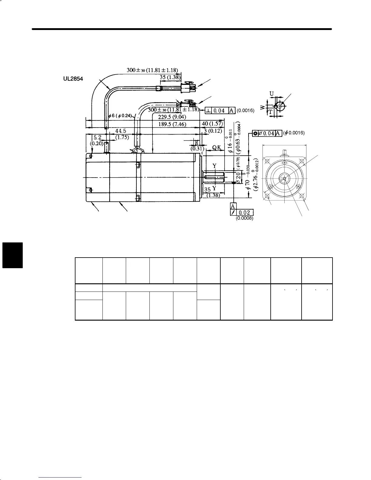
• 750 W (1.01 HP)
Encoder Lead
Encoder Plug
Motor Plug
Protective Tube
(Black)
Incremental Encoder
2048 P/R
Cross-section Y-Y
Holding Brake
(Deenergisation Operation)
Voltage: 90 VDC, Dissipated
current (Reference): 0.15 A
Brake Holding Torque= Motor Rated Torque
Brake
Lead
Motor Lead (Teflon wire) AWG22
UL1828 or UL3534
34 (1.34) 111 (4.37)
15 (0.59)
Screw
4-φ7(φ0.28)
MTG Holes
Shaft end screw hole
(SGM-
08
A316B,
with key type only)
80 (3.15)
4−R8.2
φ90
(φ3.54)
Type
SGM-
QK U W T Screw
dimen-
sions
Output
W
(HP)
Approx.
mass
kg
(lb)
Allowable
radial
load
N (lb)
Allowable
thrust
load
N (lb)
08A312B No key
−
750
4.3
392 (88.1) 147 (33.0)
08A314B
30
3
5
5
(1.01) (9.48)
08A316B
(1.18) (0.12) (0.20) (0.20)
M5,
depth 8
(0.31)
Note 1) The detector uses an incremental encoder 2048 P/R.
2) Type “A” indicates 200 V specification.
3) “08A314B” and “08A316B” have a keyed shaft. The keyway complies with JIS B
1301-1976 (precision). A straight key is supplied.
4) The quoted allowable radial load is the value at a position 35 mm (1.38 in.) from the mo-
tor mounting surface.
5) The electromagnetic brake is only to hold the load in position and cannot be used to stop
the motor.
5

 Loading...


