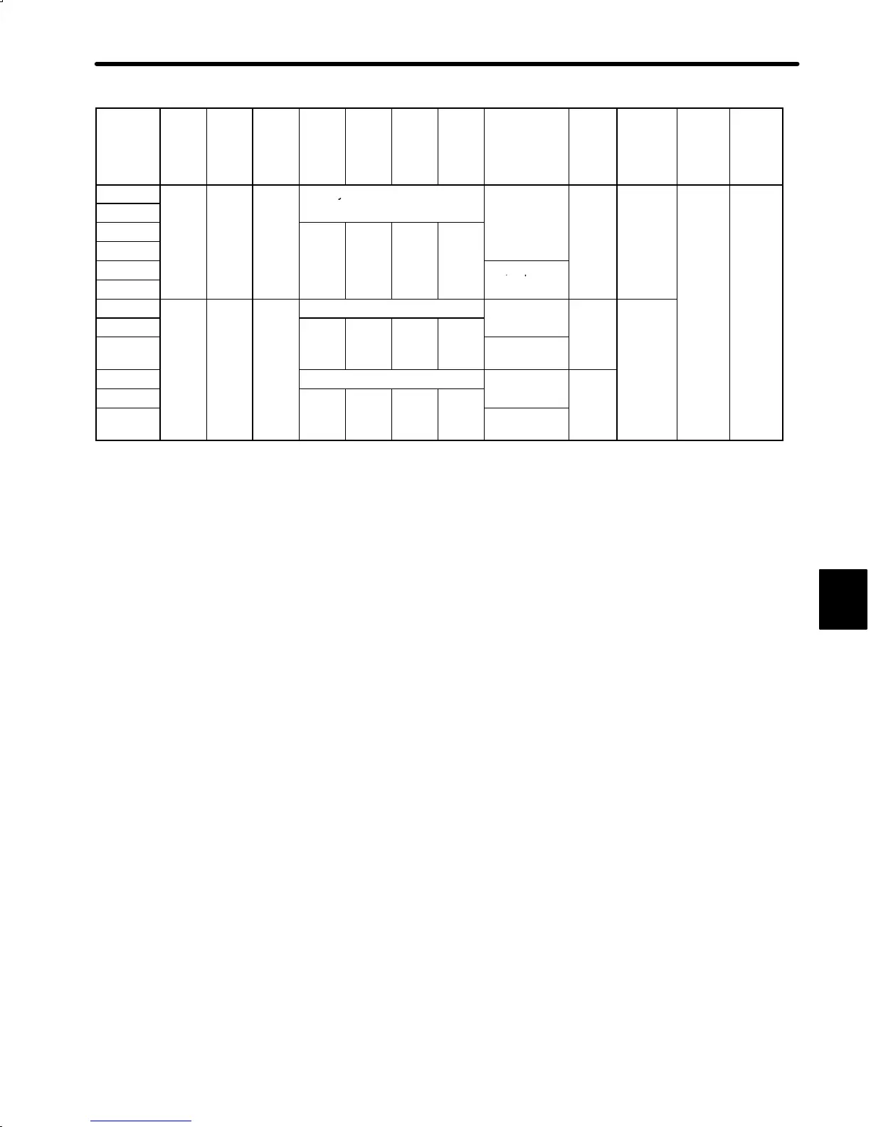
5.4 Σ-Series Dimensional Drawings
255
Type
SGM-
L LL LM QK U W T Screw
dimensions
Out-
put
W
(HP)
Approx.
mass
kg
(lb)
Allow-
able
radial
load
N (lb)
Allow-
able
thrust
load
N (lb)
02A312B
166.0
136.0
62.5
No key
−
200
1.6
245
74
02B312B
(6.54) (5.35) (2.46)
(0.27) (3.53) (55.1) (16.6)
02A314B
20
3
5
5
02B314B
(0.79) (0.12) (0.20) (0.20)
02A316B
M5, depth 8
02B316B
(0.31)
03B312B
194.0
164.0
90.5
No key
−
300
2.2
03B314B
(7.64) (6.46) (3.56)
20
3
5
5
(0.40) (4.85)
03B316B
(0.79) (0.12) (0.20) (0.20)
M5, depth 8
(0.31)
04A312B No key
−
400
04A314B
20
3
5
5
(0.53)
04A316B
(0.79) (0.12) (0.20) (0.20)
M5, depth 8
(0.31)
Note 1) The detector uses an incremental encoder 2048 P/R.
2) Type “A” indicates 200 V specification, and type “B” indicates 100 V specification.
3) “02A(B)314B”, “02A(B)316B”, “03B314B”, “03B316B”, “04A314B” and “04A316B” have
a keyed shaft. The keyway complies with JIS B 1301-1976 (precision). A straight key is
supplied.
4) The quoted allowable radial load is the value at a position 25 mm (0.98 in.) from the mo-
tor mounting surface.
5) The electromagnetic brake is only to hold the load in position and cannot be used to stop
the motor.
5

 Loading...


