RELATIONSHIP BETWEEN REFERENCE FORMS AND USER CONSTANTS
482
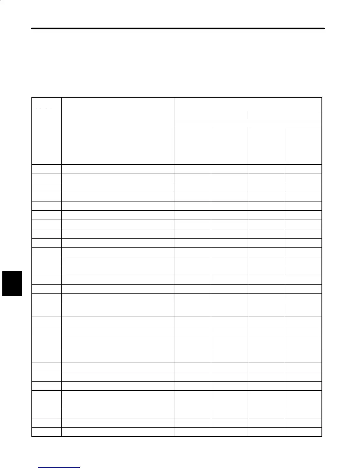
Relationship between Reference Forms and User Constants (1)
f
: Related to or possibly related to
×
: Not related at all
User
Constant
User Constant Name
Speed/Torque Control Mode
(Cn-02 Bit B = 0)
No.
Speed Control Torque Control
Cn-02 Bit 2 = 0
Speed
Control
(Standard)
Cn-01
Bit A = 0
Bit B = 0
Speed
Control with
Zero-clamp
Function
Bit A = 1
Bit B = 0
Torque
Control I
Bit A = 0
Bit B = 1
Torque
Control II
Bit A = 1
Bit B = 1
Cn-03 Speed reference gain
f f
×
f
Cn-04 Speed loop gain
f f f f
Cn-05 Speed loop integration time constant
f f
×
×
Cn-06 Emergency stop torque
f f
×
f
Cn-07 Soft start time (acceleration)
f f
×
f
Cn-08 Forward torque limit
f f f f
Cn-09 Reverse torque limit
f f f f
Cn-0A Encoder pulse dividing ratio
f f f f
Cn-0B Zero-speed level
f f f f
Cn-0C Mode switch (torque reference)
f f
×
×
Cn-0D Mode switch (speed reference)
f f
×
×
Cn-0E Mode switch (acceleration)
f f
×
×
Cn-0F Mode switch (error pulse)
× ×
×
×
Cn-10 JOG speed
f f f f
Cn-11 Number of encoder pulses
f f f f
Cn-12 Time delay from brake reference until servo
OFF
f f f f
Cn-13 Torque reference gain
f f f f
Cn-14 Speed limit for torque control I
f f f
×
Cn-15 Speed level for brake reference output during
motor operation
f f f f
Cn-16 Output timing of brake reference during
motor operation
f f f f
Cn-17 Torque reference filter time constant
f f f f
Cn-18 Forward external torque limit
f f f f
Cn-19 Reverse external torque limit
f f f f
Cn-1A Position loop gain
×
f
×
×
Cn-1B Position complete range
× ×
×
×
Cn-1C Bias
× ×
×
×
Cn-1D Feed forward
× ×
×
×
Cn-1E Overflow
× ×
×
×
F

 Loading...


