493
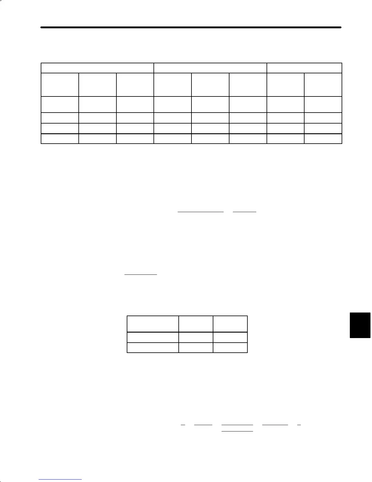
• When detector EXE650B (interpolation magnification: 25) is used:
8MHz Clock
10MHz Clock Switching
Max. Input
Frequency
fE max
Min. Edge
Interval
a min
Min. Pulse
Width
b min
Max. Input
Frequency
fE max
Min. Edge
Interval
a min
Min. Pulse
Width
b min
S3 S4
Approx.
60kHz
0.125µs 0.125µs
Approx.
60kHz
0.1µs 0.1µs
× ×
40kHz
0.25µs 0.25µs
50kHz
0.2µs 0.2µs
−
×
20kHz
0.5µs 0.5µs
25kHz
0.4µs 0.4µs
×
−
10kHz
1.0µs 1.0µs
12.5kHz
0.8µs
0.8s
− −
(×: Switch is closed)
2) Application Review
a) Linear Scale :
Input Frequency =
Operation Speed
Scale Interval
=
1200∕60
0.01
= 2000PPS < EXE650B Max.InputFrequency
b) Min. Edge Interval and Pulse Width
DR2 receivable max. frequency : 675kHz
10
6
675000 × 4
= 0.3704 μs < Min. Edge Interval
• With the above a) and b), switching S
3
and S
4
at 8MHz clock can be performed under
both of the following conditions:
Max. Input
Frequency
S
3
S
4
20kHz
×
−
10kHz
− −
c) Feedback Frequency to Detector Output Frequency and Error Counter
Detector Output Frequency = 2000 ×25 = 50000PPS ! 50kPPS
Feedback Frequency = 50 ×4 = 200kPPS
d) DR2 User Constant (Cn-24, -25)
* Electronic Gear =
B
A
=
Cn–24
Cn–25
=
Cn–2A × 4
4×6
0.0001×10
=
6000 × 4
24000
=
1
1
G

 Loading...


