APPLICATIONS OF Σ-SERIES PRODUCTS
3.1.3 Restricting Torque cont.
58
User Constant Setting:
Memory switch (Cn-01) bit 4 = 0
Sets the maximum torque values for
forward rotation and reverse rotation,
respectively.
Sets these user constants when torque
must be restricted according to ma-
chine conditions.
This torque restriction function always
monitors torque, and outputs the signal
shown on the right when the limit value
is reached.
Specifies a torque limit value in terms of
a percentage of the rated torque.
Output Signal for Torque Restric-
tion Function
D CLT
+ (1CN-25), CLT- (1CN-26)
D Status indication mode bit data
D Monitor mode (Un-05) bit 4
Example of Use: Machine Protection
Motor speed
Torque limit
Torque
Note that too small a torque limit val-
ue will result in torque shortage at ac-
celeration or deceleration.
• Using CLT
+, CLT- Signals
This section describes how to use contact output signals CLT
+, CLT- as a torque limit
output signal.
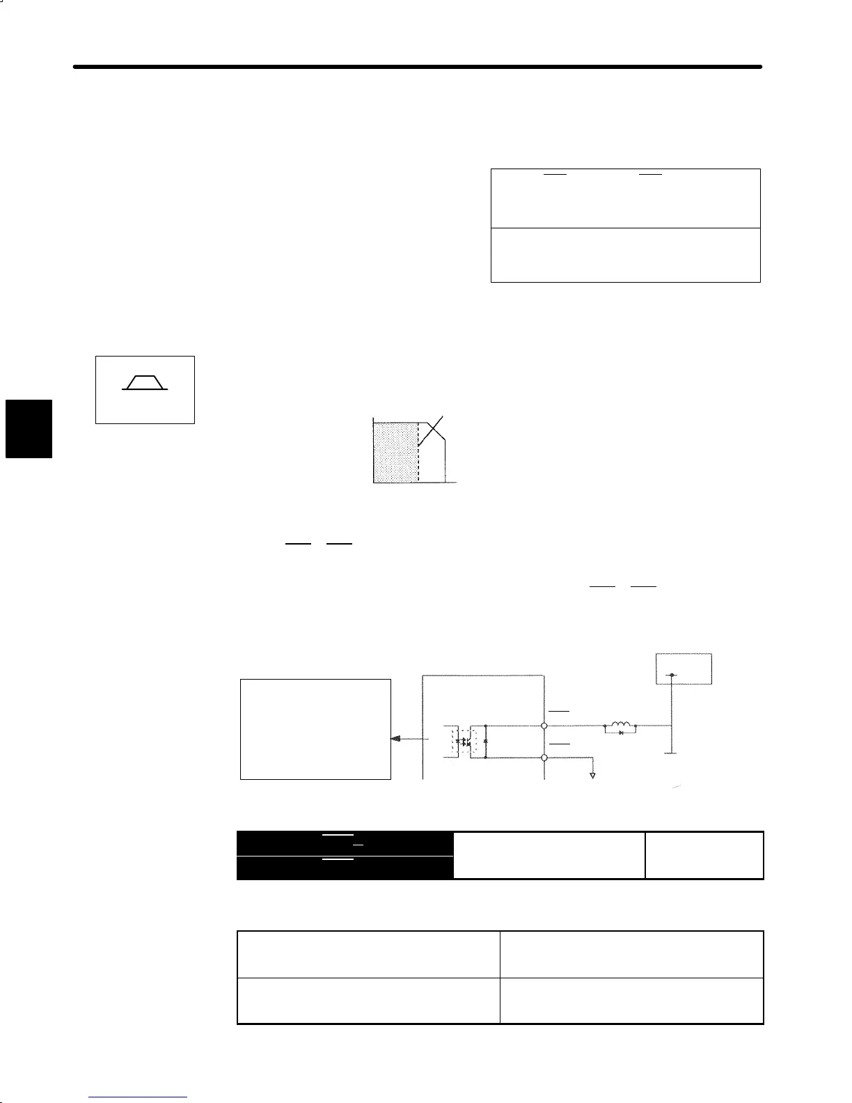
Photocoupler Output
Per output:
Maximum operation
voltage: 30 VDC
Maximum output
current: 50 mA DC
Servopack
I/O power
supply
+24V
1CN-25
1CN-26
CLT
+
CLT
-
Output → CLT+ 1CN-25
Torque Limit Output (Running
For Speed/Torque
Output → CLT- 1CN-26
u
pu
on
ro
This signal indicates whether motor output torque (current) is being restricted.
ON status: The circuit between 1CN-25 and
1CN-26 is closed.
1CN-25 is at low level.
Motor output torque is being restricted.
(Internal torque reference is greater than the
preset value.)
OFF status: The circuit between 1CN-25 and
1-CN26 is open.
1CN-25 is at high level.
Motor output torque is not being restricted.
(Internal torque reference is equal to or below
the preset value.)
3
Speed

 Loading...


