3.1 Setting User Constants According to Machine Characteristics
59
Preset Value: Cn-08 (TLMTF)
Cn-09 (TLMTR)
Cn-18 (CLMIF) : P-CL
input only
Cn-19 (CLMIR) : N-CL
input only
Note This function is changed to another function depending on the setting of bit 4 of
memory switch Cn-01.
To use output signals CLT
+, CLT- as a torque limit output signal, set the following memory
switch to 0.
This memory switch can also be used to set level 2 torque restriction (described in the
next subsection).
Cn-01 Bit 4
CLT+, CLT-
Output Signals
Selection
Factory
Setting: 0
For Speed/Torque Control
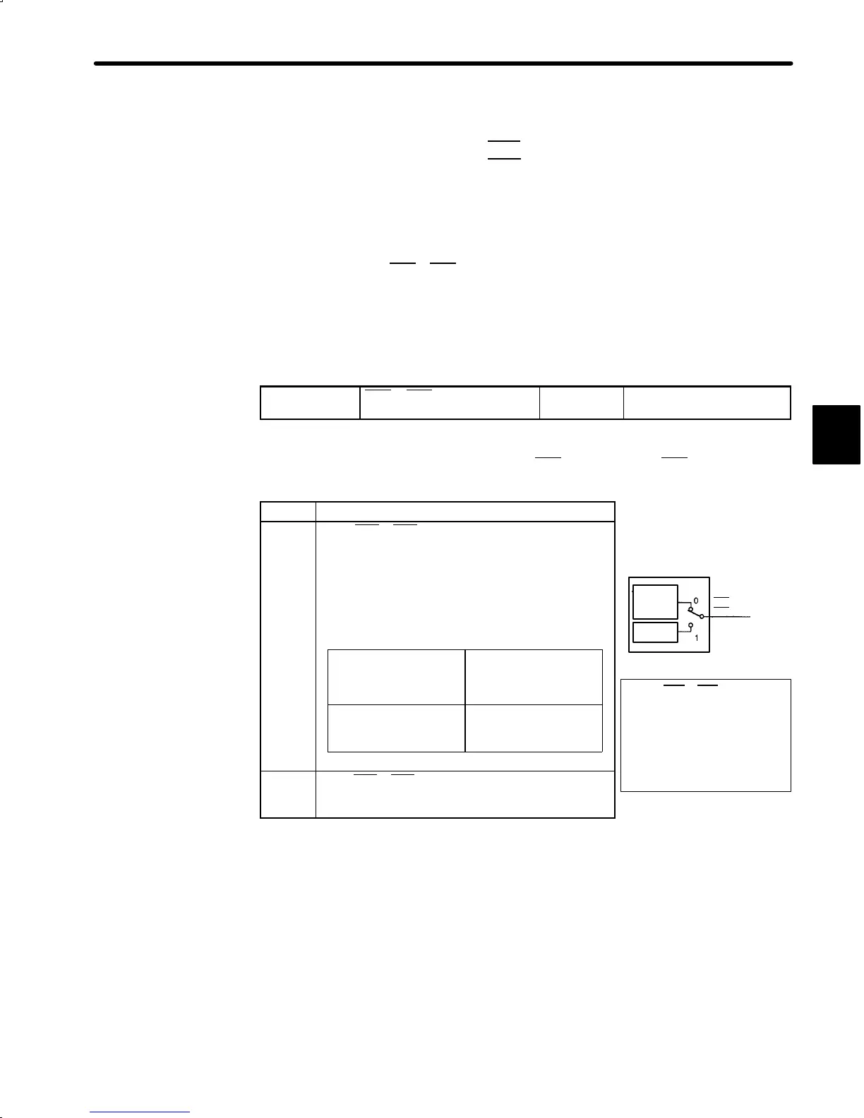
Sets the output conditions for output signals CLT+ (1CN-25) and CLT- (1CN-26).
Setting Meaning
Uses CLT+, CLT- output signals as a torque
limit output signal.
Compares the DR2 Servopack internal torque
(current) reference with the preset value.
Preset Value: Cn-08 (TLMTF)
Cn-09 (TLMTR)
Cn-18 (CLMIF): P-CL input only
Cn-19 (CLMIR): N-CL input only
Internal torque
(current) reference
≧preset value
Opens the circuit
between 1CN-25 and
1CN-26
Internal torque
(current) reference <
preset value
Closes the circuit
between 1CN-25 and
1CN-26
1
Uses CLT+, CLT- output signals as a speed
coincide output signal.
For details, refer to 3.7.4.
3
Bit 4 of memory switch Cn-01
Torque
limit
detection
Speed
coincide
When CLT+, CLT- output
signals are changed, the
following bit data are also
changed:
• Status indication mode bit
data
• Monitor mode Un-05 bit 4
CLT+
CLT-
(1CN-25)
(1CN-26)

 Loading...


