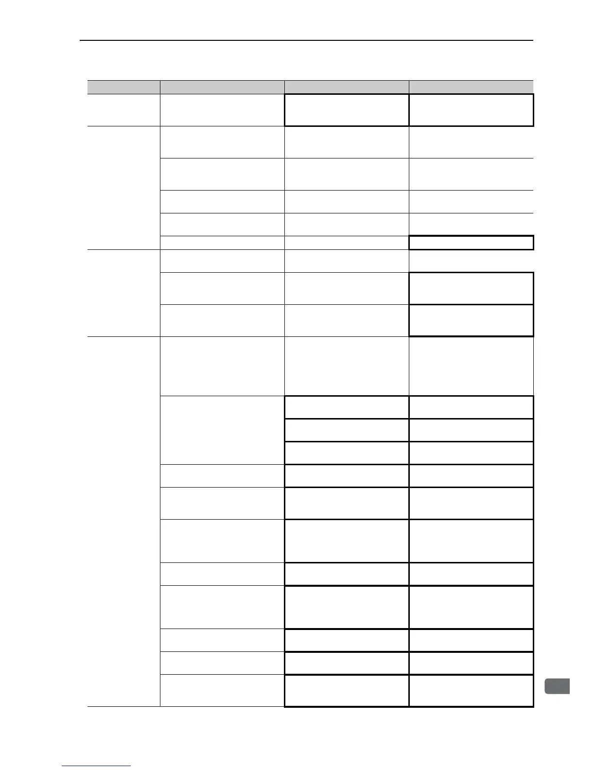
Servomotor
Speed Unstable
Wiring connection to servomotor is
defective.
Check connections of main circuit
cable (phases-U, -V, and -W) and
encoder connectors.
Tighten any loose terminals or con-
nectors.
Servomotor
Rotates Without
Reference Input
Speed control: Speed reference
input is incorrect.
Check V-REF and SG to confirm if
the control method and the input are
agreed.
Correct the control mode selection
parameter, or the input signal.
Torque control: Torque reference
input is incorrect.
Check V-REF and SG to confirm if
the control method and the input are
agreed.
Correct the control mode selection
parameter, or the input signal.
Speed reference offset is incorrect.
The SERVOPACK offset is
adjusted incorrectly.
Adjust the SERVOPACK offset.
Position control: Reference pulse
input is incorrect.
Check Pn200.0 reference pulse
form or sign + pulse signal.
Correct the control mode selection
parameter, or the input signal.
A SERVOPACK fault occurred. − Replace the SERVOPACK.
Dynamic Brake
Does Not Operate
Improper Pn001 setting
Check the setting of parameter
Pn001.0.
Correct the parameter setting.
DB resistor disconnected
Check if excessive moment of iner-
tia, motor overspeed, or DB fre-
quently activated occurred.
Replace the SERVOPACK, and
lighten the load.
DB drive circuit fault −
There is a defective component in
the DB circuit. Replace the SER-
VOPACK.
Abnormal Noise
from Servomotor
The servomotor largely vibrated
during execution of tuning-less
function.
Check the servomotor speed wave-
form.
Reduce the load so that the moment
of inertia ratio becomes within the
allowable value, or increase the
load level or lower the tuning level
for the tuning-less level setting
(Fn200).
Mounting is not secured.
Check if there are any loose mount-
ing screws.
Tighten the mounting screws.
Check if there is misalignment of
couplings.
Align the couplings.
Check if there are unbalanced cou-
plings.
Balance the couplings.
Bearings are defective.
Check for noise and vibration
around the bearings.
Replace the servomotor.
Vibration source at the driven
machine
Check for any foreign matter, dam-
age, or deformations on the machin-
ery's movable parts.
Contact the machine manufacturer.
Noise interference due to incorrect
input/output signal cable specifica-
tions
The input/output signal cables must
be tinned annealed copper twisted-
pair or shielded twisted-pair cables
with a core of 0.12 mm
2
min.
Use the specified input signal wires.
Noise interference due to length of
input/output signal cable.
Check the length of the input/output
cable.
The input/output cable length must
be no more than 3 m.
Noise interference due to incorrect
encoder cable specifications.
The encoder cable must be tinned
annealed copper twisted-pair or
shielded twisted-pair cables with a
core of 0.12 mm
2
min.
Use the specified encoder cable.
Noise interference due to length of
encoder cable wiring
Check the length of the encoder
cable.
The encoder cable must be no more
than 20 m.
Noise interference due to damaged
encoder cable
Check if the encoder cable is dam-
aged or bent.
Replace the encoder cable and mod-
ify the encoder cable layout.
Excessive noise to the encoder
cable
Check if the encoder cable is bun-
dled with high-current line or near a
high-current line.
Correct the encoder cable layout so
that no surge is applied.
Problem Probable Cause Investigative Actions Corrective Actions

 Loading...


