5 Operation
5.2.4 Holding Brakes
5-10
∗1. The operation delay time of the brake is shown in the following table. The operation delay time is an example when
the power supply is turned ON and OFF on the DC side. Be sure to evaluate the above times on the actual equipment
before using the application.
∗2. After the/S-ON signal has turned ON and 50 ms has passed since the brake was released, output the reference from
the host controller to the SERVOPACK.
∗3. Use Pn506, Pn507, and Pn508 to set the timing of when the brake will be activated and when the servomotor power
will be turned OFF.
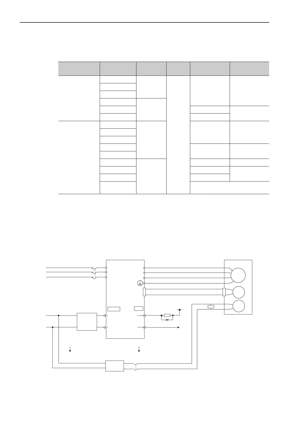
(1) Wiring Example
Use the brake signal (/BK) and the brake power supply to form a brake ON/OFF circuit. The following dia-
gram shows a standard wiring example.
The timing can be easily set using the brake signal (/BK).
Main Circuit Power
Supply Voltage
Servomotor
Model: SGMVV-
Rated Speed
[min
-1
]
Voltage
Brake Open Time
[ms]
Brake Operation
Time [ms]
Three-phase
200 VAC
2BAB
1500
24 VDC
or
90 VDC
500 max. 150 max.
3ZAB
3GAB
2BAD
8003ZAD 550 max.
320 max.
3GAD 700 max.
Three-phase
400 VAC
2BDB
1500
500 max. 150 max.3ZDB
3GDB
4EDB
550 max. 320 max.
5EDB
2BDD
800
500 max. 150 max.
3ZDD 550 max.
320 max.
3GDD 700 max.
4EDD
An SGMVV-4EDD servomotor is not
available in a model with a holding brake.
Servomotor with
holding brake
Surge
absorber
Power supply
SERVOPACK and
converter
Red
Black
Blue or yellow
White
M
BK
ENC
U
V
W
CN2
AC DC
BK-RY
BK-RY
+24 V
L1
L2
L3
(/BK+)
(/BK-)
CN1
CN101
Brake power
supply
AC side DC side
1D
0 V
0 V
24 V
24-VDC
power
supply
100/200 VAC
400 VAC
+
-
BK-R Y
: Brake control relay
A 24-VDC power supply for a 24-VDC brake is not included.
Brake power supply for 90 V Input voltage 200-V models: LPSE-2H01-E
Input voltage 100-V models: LPDE-1H01-E

 Loading...


