5.5 Torque Control
5-47
5.5 Torque Control
This section describes operation with torque control.
Input the torque reference using analog voltage reference and control the servomotor operation with the torque
in proportion to the input voltage.
Select the torque control with parameter Pn000.1.
5.5.1 Basic Settings for Torque Control
This section describes the basic settings for torque control.
(1) Signal Setting
Set the following input signals.
Maximum input voltage: ±12 VDC
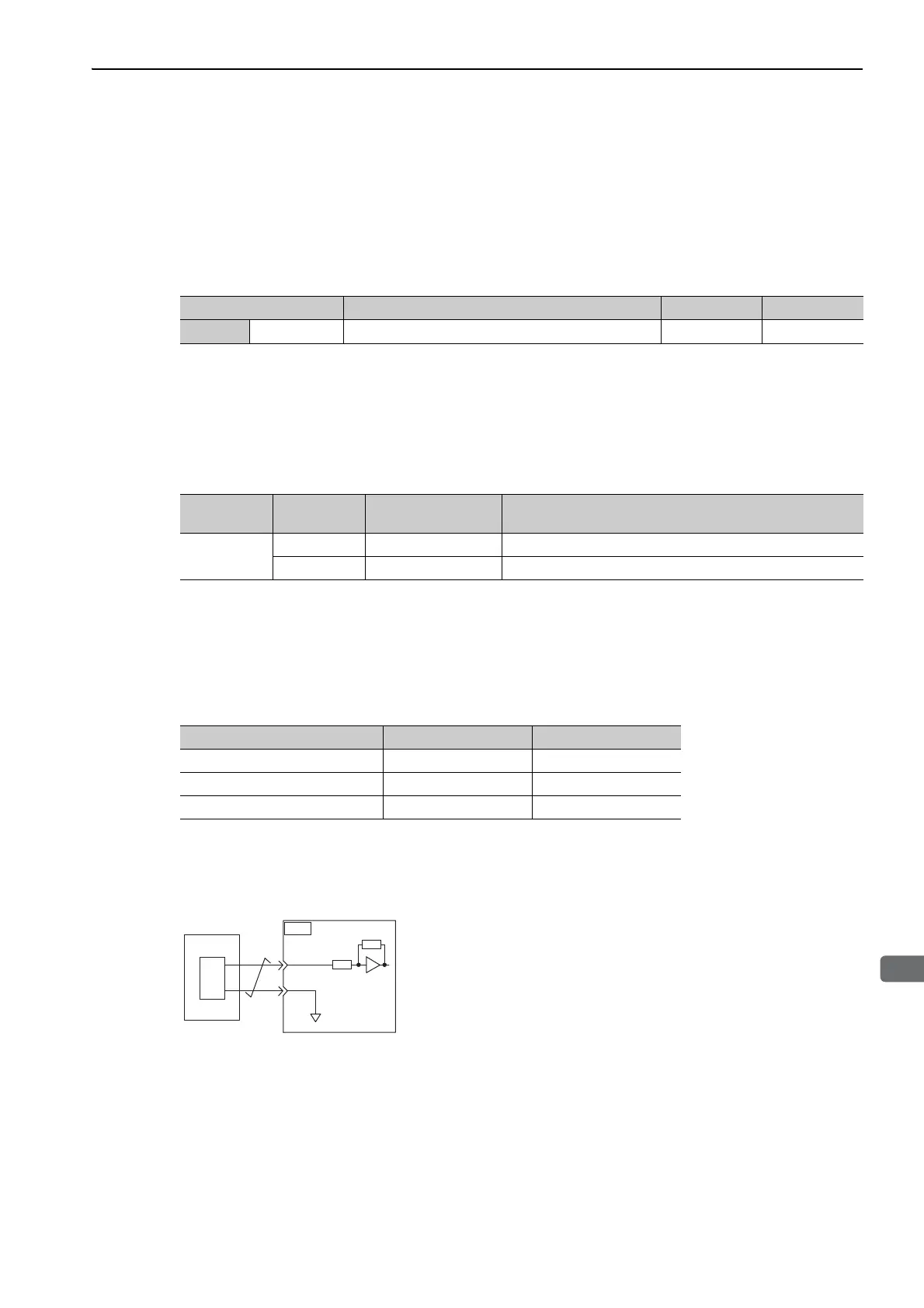
Input Circuit Example
Example
Pn400 = 0003.0 : Motor rated torque at 3.0 V [Factory setting]
Note: The value is 30, but it will be displayed on the operator as 0003.0.
Connect the pins for the T-REF signal and SG to the analog reference output terminal on the host controller
when using a host controller, such as a programmable controller, for torque control.
Note: Always use twisted-pair cables to control noise.
Parameter Meaning When Enabled Classification
Pn000
n.
2
Torque control After restart Setup
Type Signal Name
Connector
Pin Number
Name
Input
T-REF CN1-9 Torque reference input
SG CN1-10 Signal ground for torque reference input
Speed Reference Input Rotation Direction Torq ue
+3 V Forward Rated torque
+1 V Forward 1/3 rated torque
-1.5 V Reverse 1/2 rated torque
SG
CN1
10
T-REF
9
D/A
0 V
SERVOPACK
Host
controller
Approx.
14 kΩ

 Loading...


