11 Appendix
11.1.3 Connection to OMRON’s Motion Control Unit
11-4
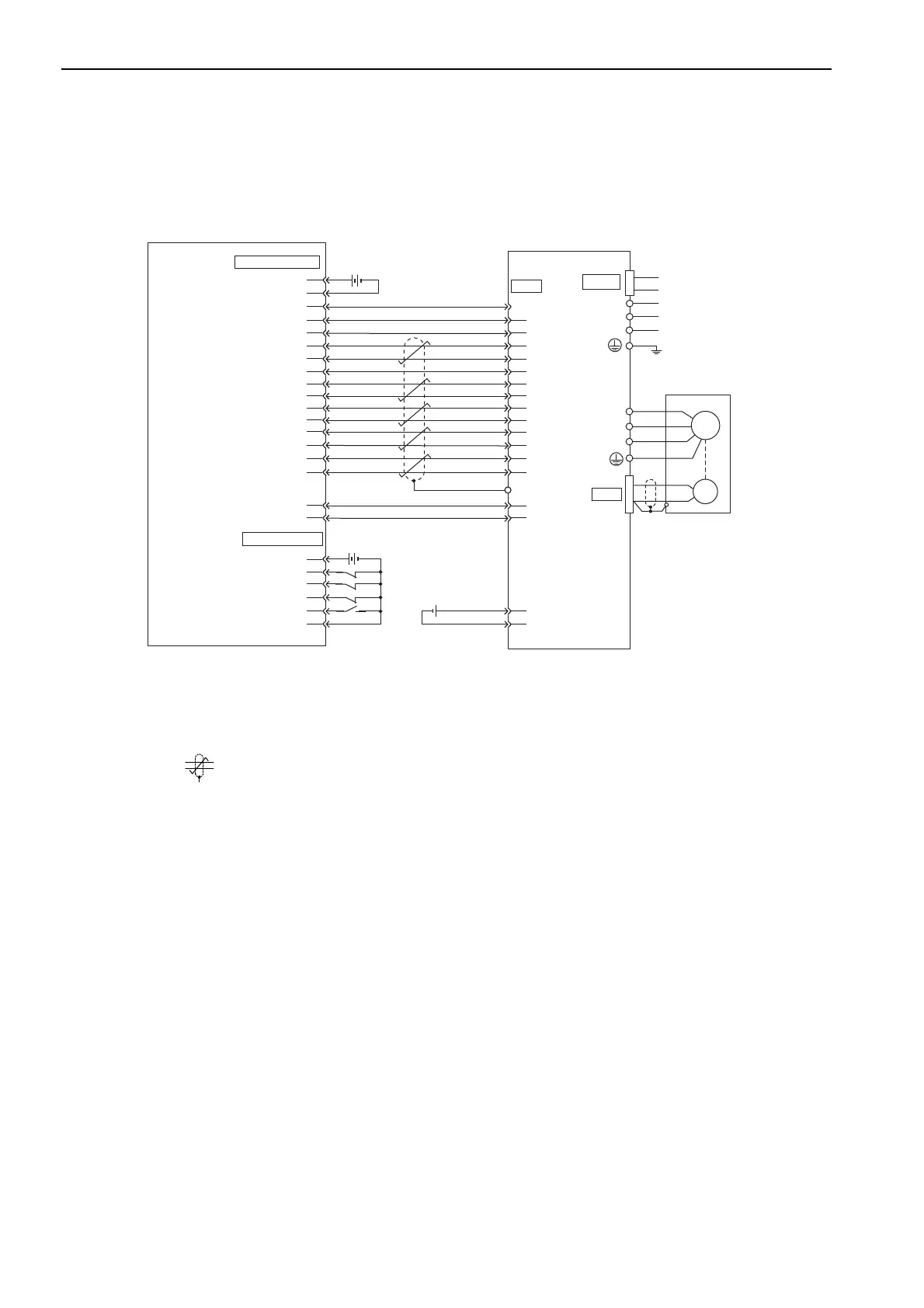
11.1.3 Connection to OMRON’s Motion Control Unit
∗1. Connect when an absolute encoder is used.
When the encoder cables with a battery case JUSP-BA01 are used, no battery is required for CN1 (between 21 and
22).
•
For CN1: ER6VC3N (3.6 V
,
2000 mA)
•
Battery case: JUSP-BA01 (3.6 V, 1000 mA)
∗2. represents twisted-pair wires.
∗3. This connection is to adjust the phase of the encoder output pulse.
Note 1. Only the signals that are related to the SERVOPACK and the OMRON Motion Control Unit are shown in the dia-
gram.
2. The main circuit power supply is a three-phase 200-VAC SERVOPACK input in the example.
3. Incorrect signal connections will cause damage to the motion control unit, SERVOPACK, or converter. Wire all
connections carefully.
4. Open the signal lines not to be used.
5. The above connection diagram shows the connections for only one axis. When using other axes, make connec-
tions to the SERVOPACK in the same way.
6. Short-circuit the normally closed (NC) input terminals that are not used at the I/O connector section of the motion
control unit.
7. Make the settings so that the servomotor can be turned ON/OFF by the Servo ON signal (/S-ON).
8. The SERVOPACK incorporates safety functions to protect people from the hazardous operation of the movable
parts of the machines, reduce the risk, and ensure the safety of the machine in operation. Necessary circuits and
settings are required in CN8 to use these functions. If these functions are not used, use the SERVOPACK with the
enclosed safety jumper connected to CN8. For details, refer to 5.11 Safety Function.
CN1
3
4
5
16
8
9
13
12
11
19
15
14
18
1
5
6
1
19
20
L3
L2
L1
35
34
20
4
BAT(-)
36
47
32
10
10
17
2
4
6
14
1
2
2
31
33
44
21
22
40
ALM+
/S-ON
/ALM-RST
SG
SEN
SG
SG
ALM-
FG
PAO
/PAO
/PBO
PBO
PCO
/PCO
V-REF
+24 V-IN
*2
*3
*1
*1
*1
*1
*1
BAT(+)
CN2
W
V
U
M
ENC
Motion Control Unit
manufactured by OMRON Corporation
C200H-MC221
(CS1W-MC221/MC421)
(CV500-MC221/MC421)
DRV connector
Servomotor
Battery
24 V
24 VDC
24 VDC
input
24 V input ground
X
-axis alarm input
X-axis run reference output
X-axis alarm reset output
X-axis SEN signal ground
X-axis SEN signal output
X-axis feedback ground
X-axis phase-A input
X-axis phase-/A input
X-axis phase-B input
X-axis phase-/B input
X-axis phase-Z input
X-axis phase-/Z input
X-axis speed reference
Axis speed reference ground
24 V output
24 V output ground
I/O connector
24 V input
X-axis CW limit input
X-axis CCW limit input
X-axis immediate stop input
X-axis origin proximity input
24 V input ground
Shell
Control
power supply
Main circuit
power supply
2.8 to 4.5 VDC
SERVOPACK and converter
CN101

 Loading...


