6 Adjustments
6.1.3 Monitoring Operation during Adjustment
6-6
6.1.3 Monitoring Operation during Adjustment
Check the operating status of the machine and signal waveform when adjusting the servo gain. Connect a mea-
suring instrument, such as a memory recorder, to connector CN5 analog monitor connector on the SERVO-
PACK to monitor analog signal waveform.
The settings and parameters for monitoring analog signals are described in the following sections.
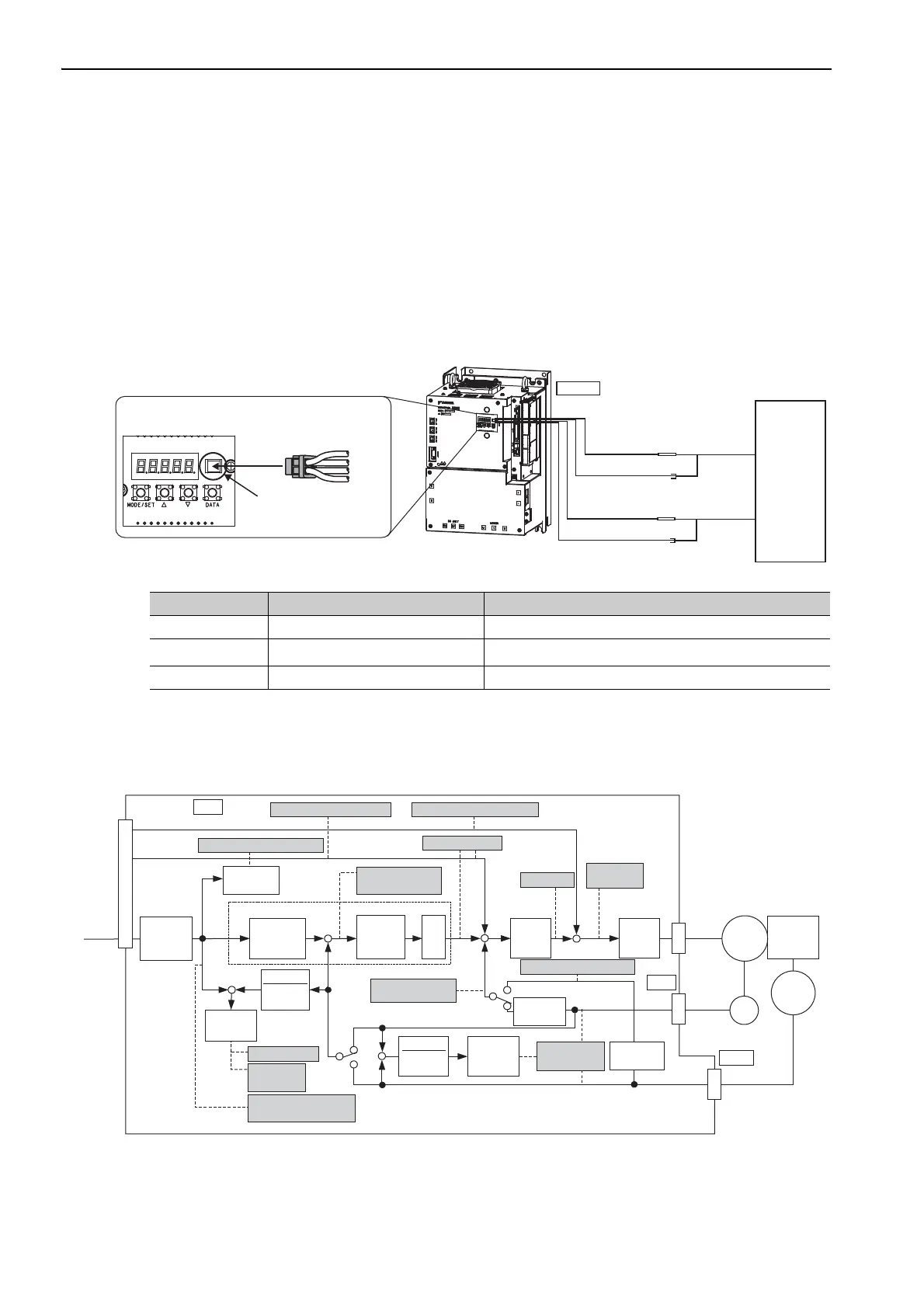
(1) Connector CN5 for Analog Monitor
To monitor analog signals, connect a measuring instrument with cable (JZSP-CA01-E) to the connector CN5.
(2) Monitor Signal
The shaded parts in the following diagram indicate analog output signals that can be monitored.
∗ Available when the fully-closed loop control is being used.
Line Color Signal Name Factory Setting
White Analog monitor 1 Torque reference: 1 V/100% rated torque
Red Analog monitor 2
Motor speed: 1 V/1000 min
-1
Black (2 lines) GND Analog monitor GND: 0 V
Probe GND
Measuring probe
Measuring
instrument*
Probe GND
Measuring probe
White
Red
Black
Black
CN5
CN5
JZSP-CA01-E
White
Red
Black
Black
Connection Example
∗ Measuring instrument is not included.
Analog
(U/V/W)
−
++
−
+
+ +
T-REF
V-REF
PULS
SIGN
+
−
−
+
1
SERVOPACK
Speed feedforward
Position reference speed
Position
amplifier error
Motor rotational
speed
Speed reference
Active gain
Torque
reference
Speed
conversion
Electronic
gear
Speed
loop
Current
loop
Fully-closed
loop control
Electronic
gear
1
Electronic
gear
Position loop
Torque feedforward
Error
counter
Error
counter
Error
counter
Load
MKp
Position error
Positioning
completed
Completion of position
reference
External encoder speed
Speed
conversion
Speed
conversion
Motor - load
position error
CN31
ENC
CN2
CN 1
External
ENC
*
*
*
*
Reference
Pulse
Multiplier
× n

 Loading...


