11.1 Connection to Host Controller
11-3
4. Incorrect signal connections will cause damage to the machine controller, SERVOPACK, or converter. Wire all
connections carefully.
5. Open the signal lines not to be used.
6. The above connection diagram shows the connections for only one axis. When using other axes, make connec-
tions to the SERVOPACK in the same way.
7. Short-circuit the normally closed (NC) input terminals that are not used at the I/O connector section of the
machine controller.
8. Make the settings so that the servomotor can be turned ON/OFF by the Servo ON signal (/S-ON).
9. The SERVOPACK incorporates safety functions to protect people from the hazardous operation of the movable
parts of the machines, reduce the risk, and ensure the safety of the machine in operation. Necessary circuits and
settings are required in CN8 to use these functions. If these functions are not used, use the SERVOPACK with the
enclosed safety function jumper connector connected to CN8. For details, refer to 5.11 Safety Function.
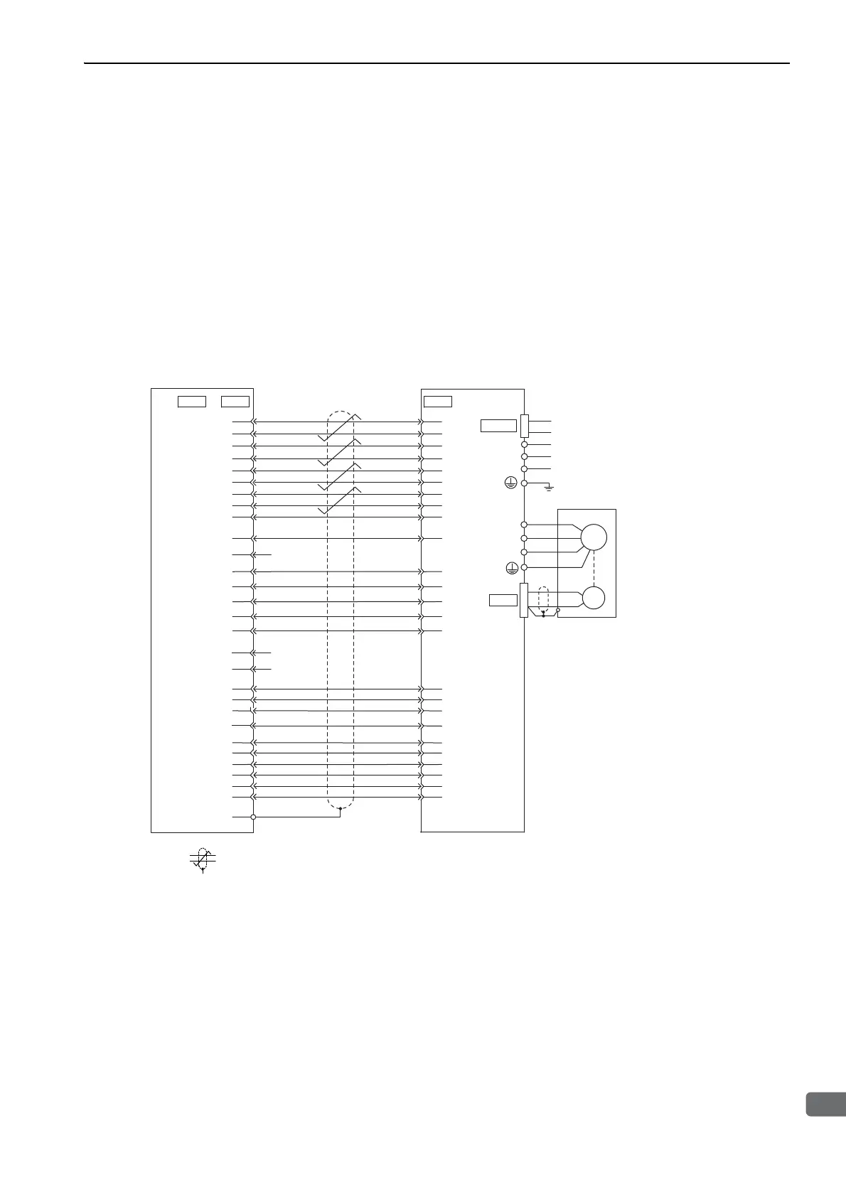
11.1.2 Connection to MP920 Servo Module SVA-01A
∗ represents twisted-pair wires.
Note 1. Connection cables (model: JEPMC-W6050-) to connect the SERVOPACK to the MP920 are prepared by
Yaskawa. For details, refer to Machine Controller MP920 User’s Manual design and maintenance (No.: SIEZ-
C887-2.1).
2. Only signals related to the SERVOPACK and MP920 Servo Module SVA-01A are shown in the diagram.
3. The main circuit power supply is a three-phase 200-VAC SERVOPACK input in the example.
4. Incorrect signal connections will cause damage to the machine controller, SERVOPACK, or converter. Wire all
connections carefully.
5. Open the signal lines not to be used.
6. The above connection diagram shows the connections for only one axis. When using other axes, make connec-
tions to the SERVOPACK in the same way.
7. Short-circuit the normally closed (NC) input terminals that are not used at the I/O connector section of the
machine controller.
8. Make the settings so that the servomotor can be turned ON/OFF by the Servo ON signal (/S-ON).
9. The SERVOPACK incorporates safety functions to protect people from the hazardous operation of the movable
parts of the machines, reduce the risk, and ensure the safety of the machine in operation. Necessary circuits and
settings are required in CN8 to use these functions. If these functions are not used, use the SERVOPACK with the
enclosed safety jumper connected to CN8. For details, refer to 5.11 Safety Function.
CN1 CN1CN4
3
4
5
16
7
6
13
12
30
34
29
11
19
14
1
20
28
32
FG
21
22
18
35
10
17
31
2
23
24
20
6
43
42
41
47
4
27
32
30
28
10
29
31
5
2
33
34
35
36
19
44
21
22
40
NREF
SG
PA
PAL
PB
PBL
PC
PCL
SG
+24 V OUT
SVON
ALMRST
PCON
OTR
OTF
DOSEN
0 V
SEN
SG
0 V
0 V
SVALM
0 V
SVRDY
BRK
BAT
0BAT
V-REF
SG
∗
SG
PAO
/PAO
PBO
/PBO
PCO
/PCO
+24 V-IN
/S-ON
/ALM-RST
/P-CON
N-OT
P-OT
SEN
SG
/S-RDY-
/TGON-
ALM+
ALM-
/S-RDY+
/TGON+
BAT(+)
BAT(-)
L3
L2
L1
CN2
W
V
U
M
ENC
SERVOPACK and
converter
MP920 Servo Module SVA-01A
manufactured by
Yaskawa Electric Corporation
to
Servomotor
Control power supply
Main circuit power supply
CN101

 Loading...


