3 Wiring and Connection
3.6.1 Encoder Signal (CN2) Names and Functions
3-42
3.6 Encoder Connection
This section describes the encoder signal (CN2) names, functions, and connection examples.
3.6.1 Encoder Signal (CN2) Names and Functions
The following table shows the names and functions of encoder signals (CN2).
∗ These do not need to be connected for an incremental encoder.
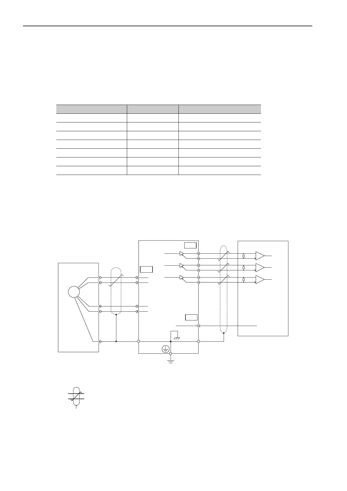
3.6.2 Encoder Connection Examples
The following diagrams show connection examples of the encoder, the SERVOPACK, and the host controller.
(1) Incremental Encoder
∗1. The pin arrangement for wiring connectors varies in accordance with the servomotor that is used.
∗2. : represents shielded twisted-pair wires.
Signal Name Pin No. Function
PG 5 V 1 Encoder power supply +5 V
PG 0 V 2 Encoder power supply 0 V
BAT (+)* 3 Battery (+)
BAT (-)* 4 Battery (-)
PS 5 Serial data (+)
/PS 6 Serial data (-)
Shield Shell –
35
0 V
SG
1
PA
O
/PAO
PBO
/PBO
PCO
/PCO
1
2
5
6
CN2
33
34
36
19
20
ENC
CN1
Incremental encoder
Connector shell
Shielded wire
Connector
shell
Phase A
Phase B
Phase C
SERVOPACK
SN75ALS175 or MC3486
manufactured by Texas
Instruments or the equivalent
∗2
∗2
CN1
∗1
PS
FG
/PS
PG5V
PG0V
0 V
Phase A
Phase B
Phase C
Host controller
R
R
R
Applicable line receiver:
R (terminating resistance): 220 to 470 Ω
Output line-driver SN75ALS174
manufactured by Texas
Instruments or the equivalent

 Loading...


