3.1 Main Circuit Wiring
3-3
3.1 Main Circuit Wiring
The names and specifications of the main circuit terminals are given below.
Also this section describes the general precautions for wiring and precautions under special environments.
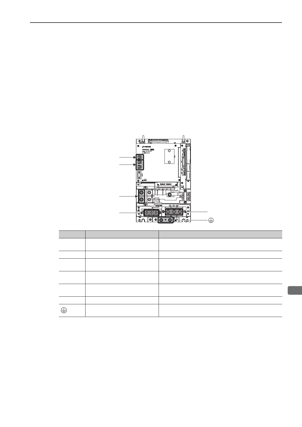
3.1.1 Main Circuit Terminals
The names and specifications of the main circuit terminals are given below.
Note: For the purpose of this description, the SERVOPACK is shown with the front cover removed. Always keep the front
cover attached when using the SERVOPACK.
SERVOPACK
CN115
U, V, W
CN103, CN104
P, N
DU, DV, DW
Terminals Name Specifications
P, N
Main circuit DC voltage input termi-
nals
Connect these terminals to the P and N terminals on the converter.
U, V, W Servomotor terminals Connect these terminals to the Servomotor terminals.
CN103,
CN104
Control power input connectors
CN103 is the 24 VDC (±15%) input. CN104 takes the same input,
but it is normally not necessary to connect it.
DU, DV,
DW
Dynamic brake unit terminals Connect these terminals to the dynamic brake unit.
CN115 Dynamic brake unit connector
Connect this connector to the DBON and DB24 terminals on the
dynamic brake unit.
+, - NC Do not connect these terminals.
Ground terminal
Connect this terminal to the power supply ground terminal and the
Servomotor ground terminal, and then ground it.

 Loading...


