3 Wiring and Connection
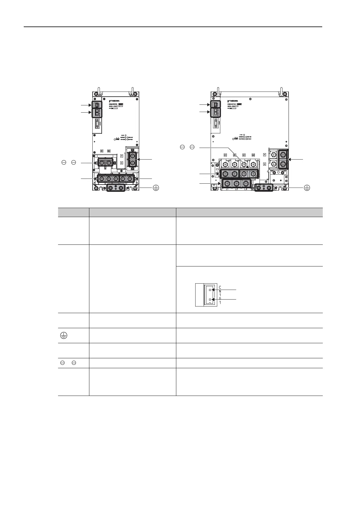
3.1.1 Main Circuit Terminals
3-4
Converter
CN101
CN103,
CN104
L1, L2, L3 B1, B2
P, N
1, ޓ2
CN101
CN103,
CN104
P, N
L1, L2, L3
B1, B2
1, ޓ2
Converter
SGDV-COA2BAA
SGDV-COA3ZDA
Converter
SGDV-COA3GAA
SGDV-COA5EDA
Terminals Name Specifications
L1, L2, L3 Main circuit power input terminals
SGDV-COAAA: Three-phase, 200 to 230 VAC, +10% to -
15%, 50/60 Hz
SGDV-COADA: Three-phase, 380 to 480 VAC, +10% to -
15%, 50/60 Hz
CN101 Control power input connector
SGDV-COAAA: Single-phase, 200 to 230 VAC, +10% to -
15%, 50/60 Hz
SGDV-COADA: 24 VDC, ±15%
Mating connector model: 231-202/026-000 (Manufactured by
Wago Company of Japan, Ltd)
P, N
Main circuit DC voltage output ter-
minals
Connect these terminals to the P and N terminals on the SERVO-
PACK.
Ground terminal
Connect this terminal to the power supply ground terminal and
then ground it.
B1, B2
Regenerative resistor connection
terminals
Connect these terminals to the regenerative resistor unit.
1, 2
DC reactor connection terminals Remove the short bar before you connect a DC reactor.
CN103,
CN104
Control power output connectors
CN103 and CN104 output 24 VDC to the SERVOPACK.
For a 400-V system, the 24-VDC (±15%) input is output unaltered
from CN103. CN104 provides the same output, but it is normally
not necessary to connect it.
Pin 2: 24 V
Pin 1: 0 V

 Loading...


