3.3 I/O Signal Connections
3-25
3.3.2 Safety Function Signal (CN8) Names and Functions
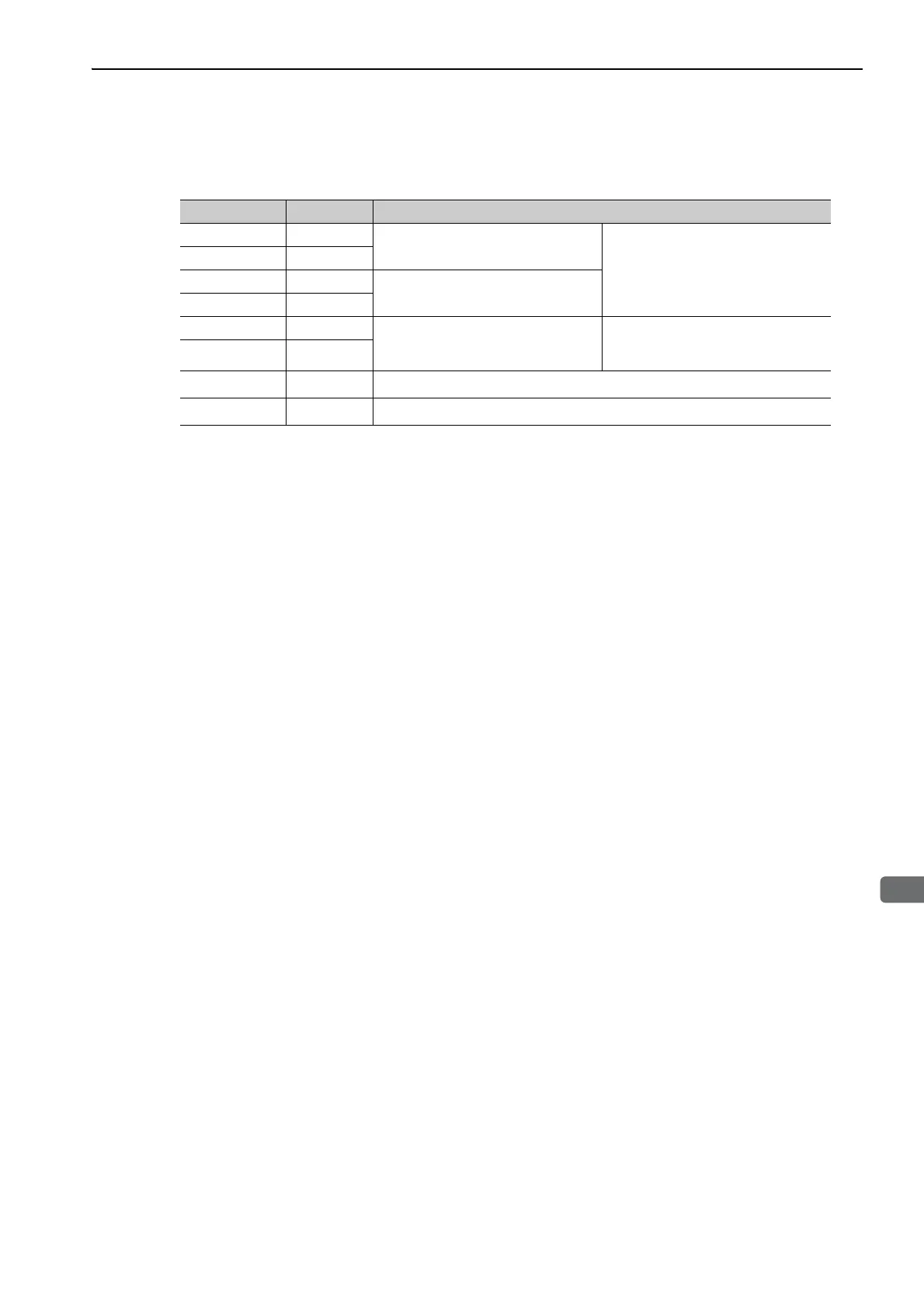
The following table shows the terminal layout of safety function signals (CN8).
∗ Do not use pins 1 and 2 because they are connected to the internal circuits.
Signal Name Pin No. Function
/HWBB1+ 4
Hard wire baseblock input 1
For hard wire baseblock input.
Baseblock (motor current off) when
OFF.
/HWBB1- 3
/HWBB2+ 6
Hard wire baseblock input 2
/HWBB2- 5
EDM1+ 8
Monitored circuit status output 1
ON when the /HWBB1 and the
/HWBB2 signals are input and the
SERVOPACK enters a baseblock state.
EDM1- 7
–
1
*
–
–
2
*
–

 Loading...


