5.4 Position Control
5-39
(4) Output Signal Setting
This output signal indicates when the multiplier of the input reference pulse has been switched for the Refer-
ence Pulse Input Multiplication Switching Input signal (/PSEL).
Note: Use parameter Pn510.2 to allocate the /PSELA signal for use. For details, refer to 3.4.2 Output Signal Allocations.
(5) Restriction
When using the following utility functions, the reference pulse input multiplication switching function is dis-
abled.
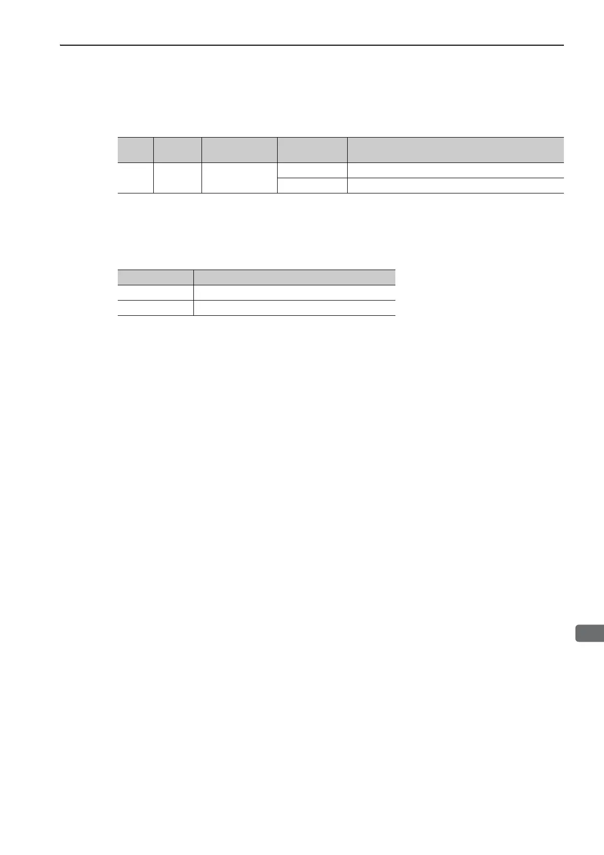
Type
Signal
Name
Connector
Pin Number
Setting Meaning
Output /PSELA Must be allocated
ON (closed) The multiplier of the input reference pulse is enabled.
OFF (open) The multiplier of the input reference pulse is disabled.
Parameter No. Function
Fn004 Program JOG operation
Fn201 Advanced autotuning

 Loading...


