5.9 Absolute Encoders
5-67
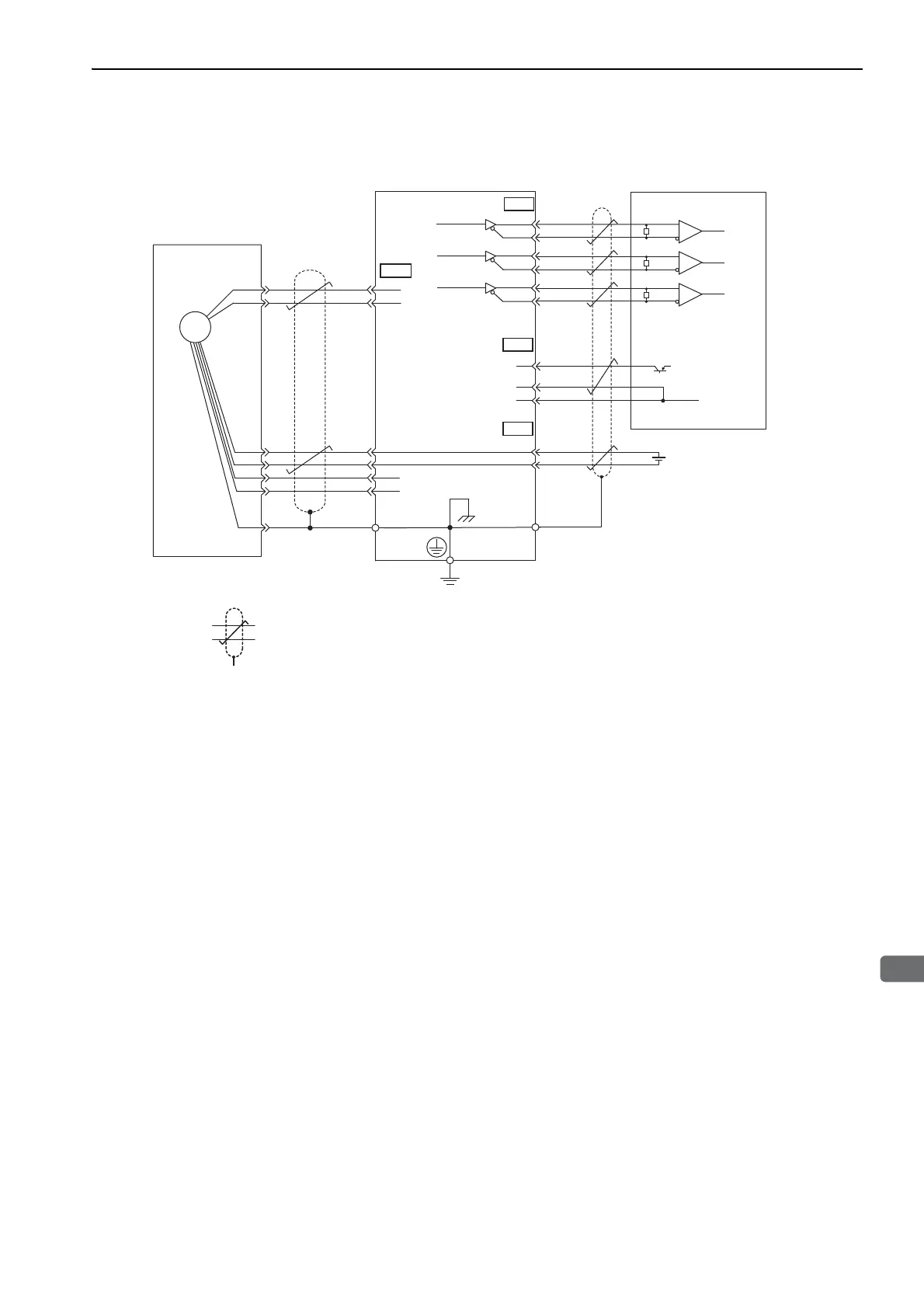
(2) Installing the Battery in the Host Controller
∗1. The absolute encoder pin numbers for the connector wiring depend on the servomotors.
∗2. : represents shielded twisted-pair wires.
∗3. When using an absolute encoder, provide power by installing an encoder cable with a JUSP-BA01-E Battery Case or
install a battery on the host controller.
/PCO
ENC
3
4
4
2
SG
SEN
21
22
BAT
BAT
(+)
(-)
CN2
33
34
35
36
19
20
CN1
SG
1
PA
O
/P
AO
PBO
/PBO
PCO
Absolute encoder
SERVOPACK
Connector
shell
Connector
shell
CN1
CN1
∗2
∗3
∗2
∗1
0 V
+5 V
Host controller
+
-
Battery
5
6
1
2
PG5 V
PG0 V
PS
FG
/PS
BAT(+)
BAT(-)
R
R
R
Applicable line receiver: SN75ALS175 or
MC3486 manufactured by Texas
Instruments or the equivalent
Terminating resistance R: 220 to 470 Ω
Phase A
Phase B
Phase C
Phase A
Phase B
Phase C
Output line-driver
SN75ALS174
manufactured by Texas
Instruments or
the equivalent

 Loading...


