1.3 Converter Part Names
1-5
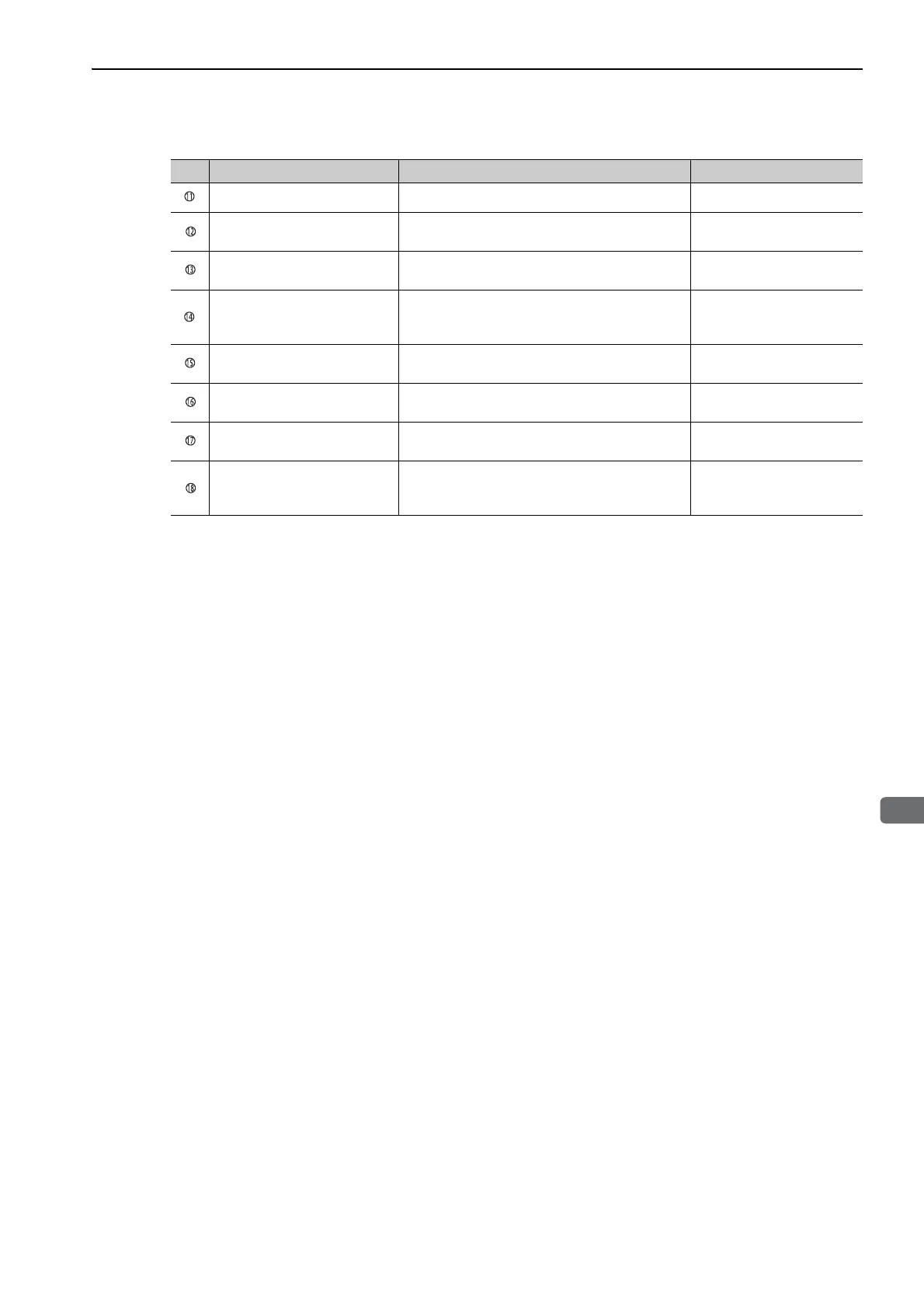
Serial number ––
Converter LED indicator
(C-RDY)
Lights (green) when the converter is ready to be
used for operations.
–
Converter LED indicator
(OVERHEAT)
Lights (red) when the converter’s heat sink is
overheated.
–
Converter LED indicator
(CHRG-ERR)
Lights (red) when the voltage between the main
circuit’s DC voltage output terminals P and N is
abnormal.
–
Converter LED indicator
(FANSTOP)
Lights (red) when an error occurs while the con-
verter fan is running.
–
Converter LED indicator
(MC-FAULT)
Lights (red) when an error occurs when the inrush
current limit relay is used.
–
Main circuit DC voltage
output terminals (P and N)
Connect these terminals to P and N on the SER-
VOPACK.
–
Regenerative resistor
connecting terminals
(B1 and B2)
Connects external regenerative resistors.
3.7 Selecting and Connect-
ing a Regenerative Resistor
Unit
(cont’d)
No. Name Description Reference

 Loading...


