9-2
IM CA150E
9.1 Calibration of Source Functions (Adjustment)
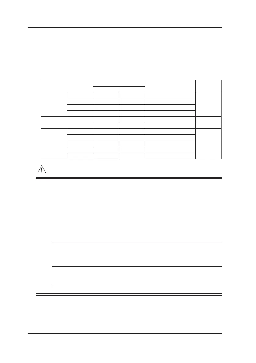
(1) Calibration Points and Calibration Ranges
Using the ▲ ▼ output setting value keys, adjust the output values so that the
readings on the standard device (CA150 source values) match the calibration
points shown below.
DCA
DCV
Calibration Point
ZERO
0 mV
0 V
0 V
0 V
0 mA
0 mA
0 mV*
0 mV*
0 mV
0 mV
0 m V
Full Scale
100.000 mV
1.00000 V
10.0000 V
30.00 V
20.000 mA
-20.000 mA
500.00 mV
2500.00 mV
500.00 mV
2500.00 mV
2500.00 mV
Condition
––
––
––
––
––
External voltage of 28 V
Excitation current of 1 mA
Excitation current of 5 mA
Excitation current of 0.1 mA
Excitation current of 0.5 mA
Excitation current of 0.05 mA
100 mV
1 V
10 V
30 V
20 mA
20 mA SINK
L 500 Ω
H 500 Ω
L 5 kΩ
H 5 kΩ
50 kΩ
Connection
Diagram
<2>
<3>
<1>
<4>
Function Range
Ω
• About Resistance (500 Ω) Internal Offset Calibration
*: When performing zero point calibration, make sure the voltage between the
H and L terminals is within approximately ±20 µV (±0.02 mV). If this value is
exceeded, the instrument needs to be repaired (internal calibration).
• About Resistance Excitation Current
When calibrating the 500 Ω and 5 kΩ ranges, two types of calibration are
required because of differences of current (excitation current) inowing
from an external device.
L 500 Ω, 1 mA Calibration with the resistance measurement range of a
L 5 kΩ, 0.1 mA digital multimeter is possible. During calibration, make sure
the resistance measurement current is the current value
shown on the left.
H 500 Ω, 5 mA Apply the current shown on the left from an external device
H 5 kΩ, 0.5 mA as shown in connection diagram <4> and then measure
the voltage drop and perform calibration.
9.1 Calibration of Source Functions (Adjustment)
 Loading...