9-6
IM CA150E
9.2 Calibration of Measurement Functions (Adjustment)
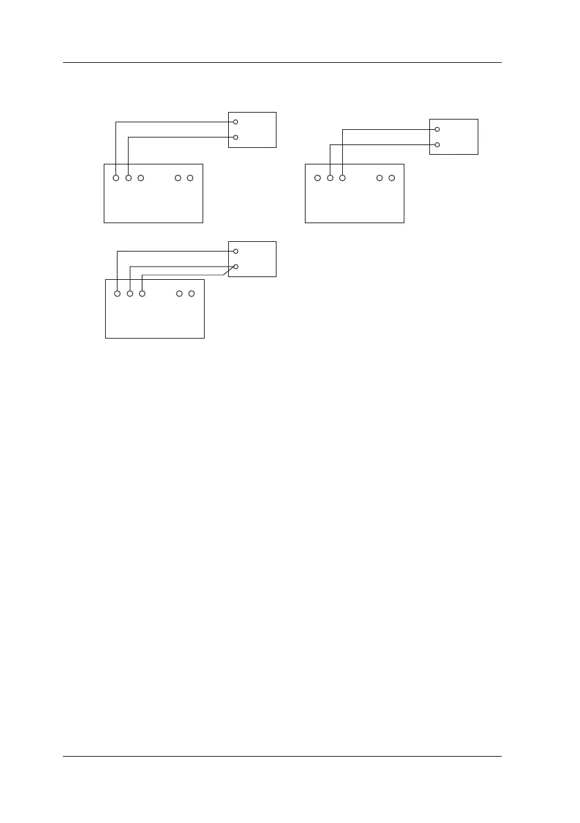
(2) Connection Diagrams
CA150
H
L
Reference Resistor
<7> Ω
H L mA
MEASURE
CA150
H L mA
MEASURE
H
L
standard
CA150
H L mA
MEASURE
H
L
DC voltage/current
standard
(3) Calibration Procedure
Connect the instrument in accordance with the function and range to be
calibrated. Refer to "(2) Connection Diagrams."
1 Simultaneously press the CLEAR and ENTER keys to switch to
setting mode.
2 Use the ▲ ▼ key to select measure (SEt MEAS).
3 Press the ENTER key to conrm the selection.
4 Use the ▲ ▼ key to select the calibration (MEAS CAL) setting.
5 Press the ENTER key to conrm the selection.
6 Use the FUNCTION and RANGE keys to set the range to calibrate.
(The + side measurement full scale value of the selected range
appears on the bottom row.)
7 Press the ENTER key to conrm the setting.
8 Start zero-point calibration:
The CAL and ZERO segments light, the input measurement value
appears on the top row, and the zero point calibration value of
the selected range appears on the bottom row.
9 Input the calibration value displayed on the bottom row into
the instrument from the standard generator.
When the input value stabilizes,
press the ENTER key to conrm the calibration value.

 Loading...