1-1
IM 04P01B01-01E
Functional Explanation and Setup Guide
For the procedure to set the functions, see section 1.10, “Function Setup Guide.”
1
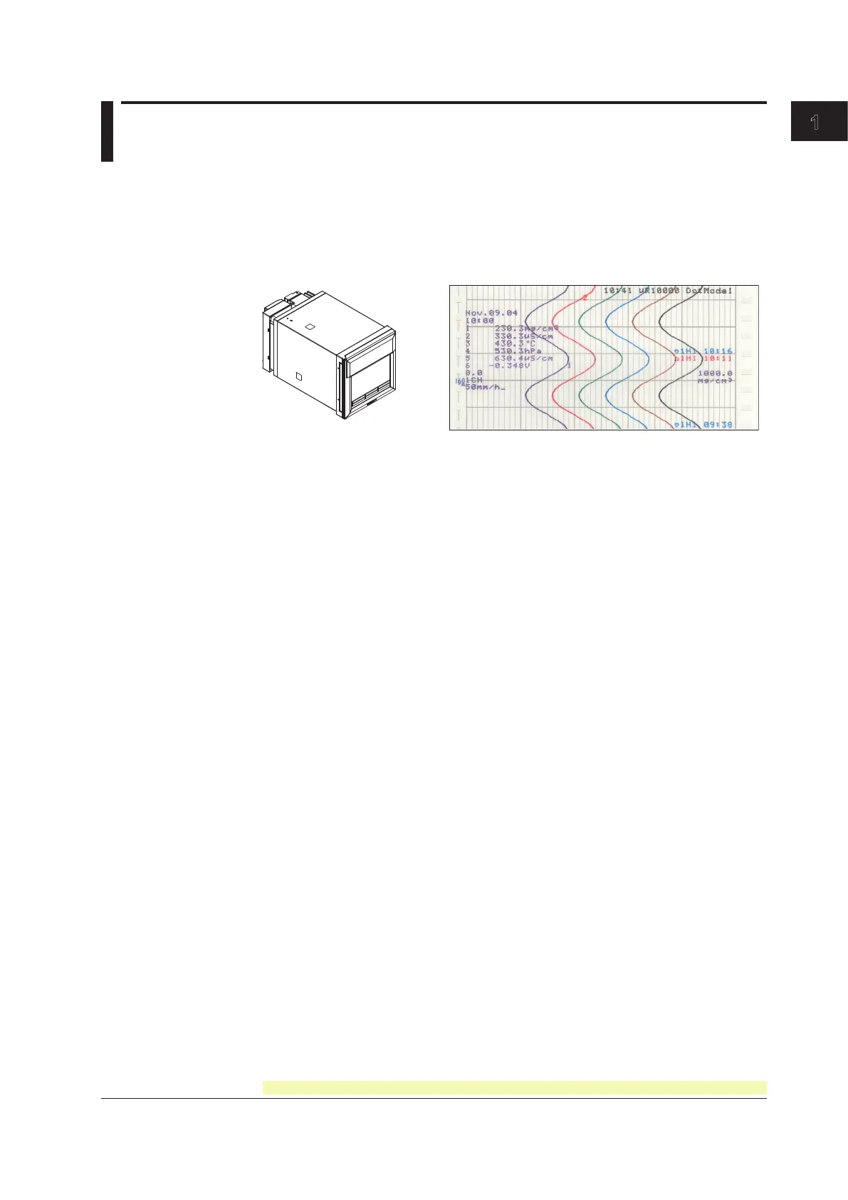
1.1 Overview of the Recorder
The µR10000 Recorder (hereafter referred to as the recorder) can be used to assign DC
voltage, 1-5V, thermocouple, RTD, and contact or voltage ON/OFF signal to channels
for measurement. The measured results are recorded with pens or dots on a chart paper
that is fed at a constant speed. The pen model can record up to 4 channels; the dot
model can record up to 6 channels.
µR10000 Recorder Recording example (dot model)
Alarms
For each channel, various alarms such as high limit alarm and low limit alarm can be
assigned to monitor the measured values. Alarm output relays can be used to output
contact signals when alarms occur (/A1, /A2, and /A3 options).
Recording
The measured results are recorded with pens or dots on a chart paper (trend recording).
The chart speed can be selected from 5 to 12000 mm/h on the pen model and 1 to 1500
mm/h on the dot model.
In addition to trend recording, various types of information can be printed or recorded
on the chart paper such as numeric measured values, alarm occurrence/release, and
predefined messages. Also, the recorder settings can be printed.
Internal Light
A light is provided for easier viewing of the recording area of the chart paper.
Display
Measured values can be displayed numerically or using bar graphs on the large display.
Also, alarm status and chart speed can be displayed.
Communication Function
Using the Ethernet communication interface (/C7 option) or the RS-422A/485
communication interface (/C3 option), the measured values on the recorder can be
output to a PC or a PC can be used to control the recorder.
This manual does not cover the communication functions. For details on communication
function, see the μR10000/μR20000 Communication Interface User’s Manual, IM
04P01B01-17E.
Other Main Functions
The computation function (/M1 option) can be used to perform various computations from
four arithmetic operations to statistical calculations on 8 and 12 computation channels on
the pen model and dot model, respectively. The computed results can be recorded.
The remote control function (/R1 option) can be used to control the start/stop and other
operations of the recorder by applying contact signals to the dedicated terminals.
The FAIL/chart end detection and output function (/F1 option) can be used to output
contact signals when errors are detected on the recorder or when the chart paper runs
out.
Chapter 1 Functional Explanation and Setup Guide
 Loading...


