General
Specications
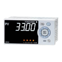
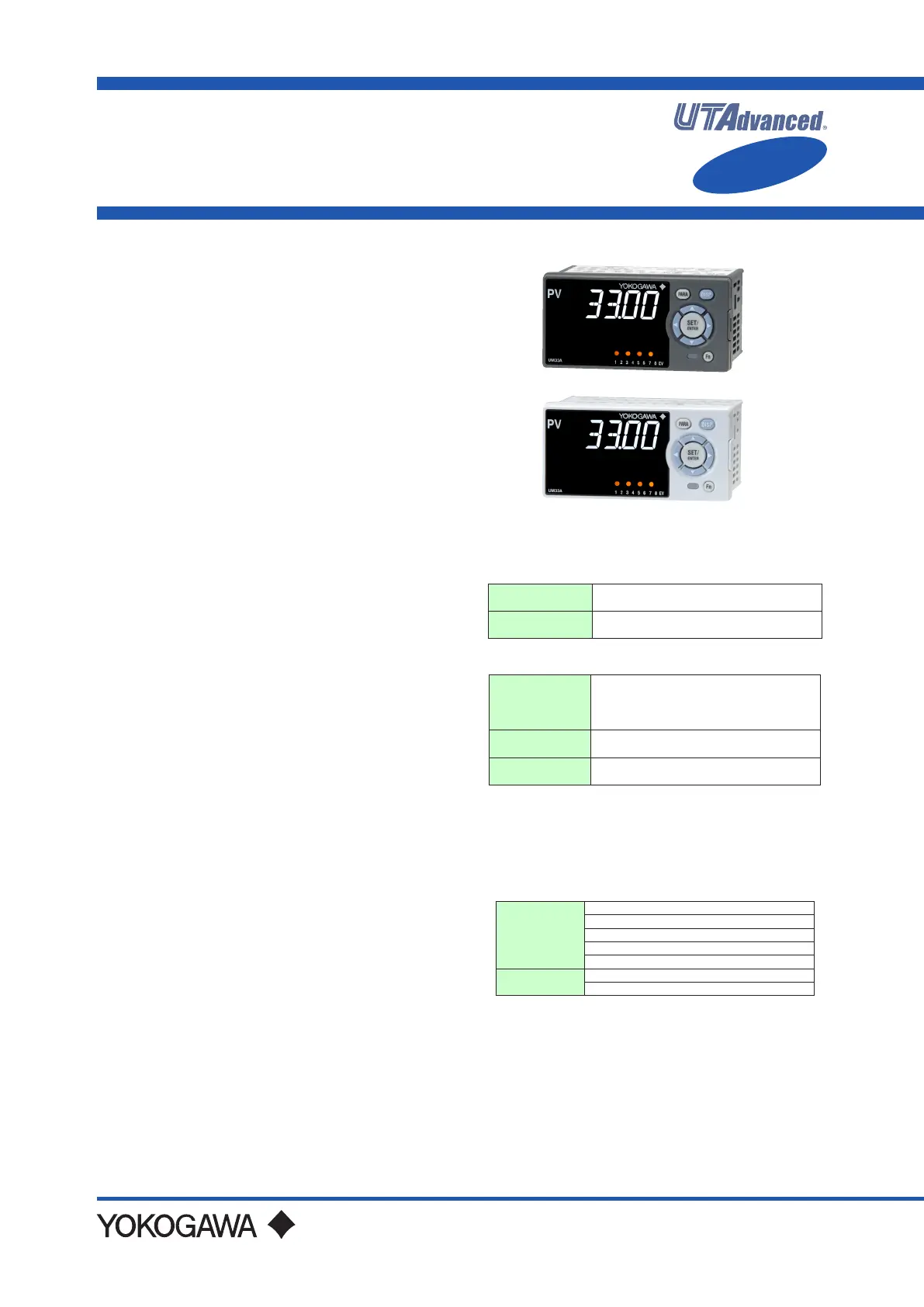
UM33A
Digital Indicator with Alarms
Yokogawa Electric Corporation
2-9-32, Nakacho, Musashino-shi, Tokyo, 180-8750 Japan
Tel.: 81-422-52-7179 Fax.: 81-422-52-6619
GS 05P03D21-01EN
GS 05P03D21-01EN
©Copyright July. 2010
6th Edition Mar.14, 2016
n Overview
The UM33A digital indicator with Alarms employ an
easy-to-read, 14-segment large color LCD display,
along with navigation keys, thus greatly increasing the
monitoring and operating capabilities. The short depth
of the controller helps save instrument panel space.
Also supporting the CC-Link communication.
n Features
• A 14-segment, active (PV display color changing
function) color LCD display is employed.
Twove-digit,high-resolutiondisplaysarepossible.
Alphabetletterscanbedisplayedinaneasy-to-read
manner. The guide display shows parameter names.
• Easy to operate
Navigation keys (SET/ENTER and Up/Down/Left/
Right arrow keys) are employed to facilitate making
settings.
• 65 mm depth
Thesmalldepthenablesthemountinginathinand
small instrumented panel.
•EmbeddedCC-Linkcommunication
SupportingeasyconnectionwithMitsubishiElectric
Corporation PLCs.
• Quick setting function
Setting only the minimum necessary parameters for
operationispossible.
• Equipped with retransmission output
• LL50A Parameter Setting Software (sold separately)
The parameters of UTAdvanced digital indicating
controllercanbebuiltfromaPCusingthissoftware.
It makes data management even easier.
• Dust-proof and drip-proof
IP66(forfrontpanel)(Notapplicabletoside-by-side
close mounting.)
NEMA4 (Hose-down test only)
nFunctionalSpecications
Signal Computation Function
Measured input computation:
Bias addition (-100.0 to 100.0% of PV input range
span.),rst-orderlaglter(timeconstantoff,1to120
s.),and10-segmentlinearizerapproximation/bias
Contact input: Retains and displays maximum and
minimumreadingsfrommeasuredvariable.
Resets the maximum and minimum readings.
Alarm Functions
• Types of Alarm
Measured value
alarm
PV (measured value) high/low limit alarm
PV rate-of-change alarm
Other alarms
Self-diagnosis alarm
FAIL
• Alarm Functions
Alarm output
action
Alarmstand-byaction
Alarm latch (forced reset) function
Alarm hysteresis
Alarm ON/OFF delay timer
Numberofalarm
settings
8
Numberofalarm
output points
Upto9(differsbymodelcode)
Contact I/O Function
This function allows for allocating the input error
condition, operation condition, alarm condition or
other conditions to the contact input and contact
output.
Contact input
PVpeakandbottomvaluesreset
Latch release (ACK)
LCDbacklightON/OFFswitch
PV red/white switch
Message interrupt displays 1 through 4
Contact output
Alarms 1 through 8
Status output
Functional
Enhancement
 Loading...