7-7
IM 05P03D21-01EN
Input (PV) Functions
7
SettingDetails
Parameter
symbol
Name
Display
level
Settingrange Menusymbol
BS PV input bias EASY
-100.0 to 100.0% of PV
input range span (EUS)
PVS
FL PVinputlter EASY OFF, 1 to 120 s
Parameter
symbol
Name
Display
level
Settingrange Menusymbol
A.BS PV analog input bias STD
-100.0 to 100.0% of each
input range span (EUS)
PV
A.FL PVanaloginputlter STD OFF, 1 to 120 s PV
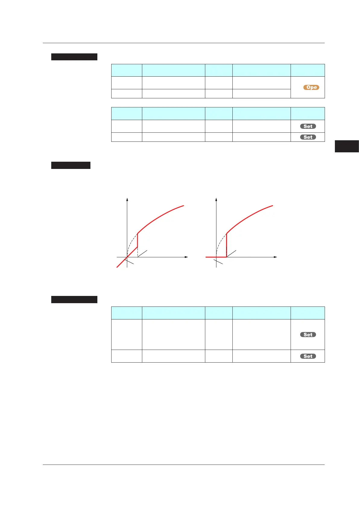
(2)SettingSquareRootExtractionandLowSignalCutoffPoint
Description
This calculation is used to convert, for example, a differential pressure signal from a
throttling flow meter such as an orifice and nozzle into a flow-rate signal. There is no
hysteresis for low signal cutoff point.
Output = Input
The slope equals “1” at levels below
the low signal cutoff point (A.SR=1).
The slope equals “0” at levels below
the low signal cutoff point (A.SR=2).
Output
Input
Output = Input
Output
Input
Low signal cutoff
point is variable.
Low signal cutoff
point is variable.
SettingDetails
Parameter
symbol
Name
Display
level
Settingrange Menusymbol
A.SR
PV analog input square root
extraction
PRO
OFF: No square root extraction.
1: Compute the square root.
(The slope equals “1.”)
2: Compute the square root.
(The slope equals “0.”)
PV
A.LC
PV analog input low signal
cutoff
PRO 0.0 to 5.0% PV
Note 1: Each parameter is displayed when the input type is voltage or current.
7.1SettingFunctionsofPVInput
 Loading...