8
All Rights Reserved. Copyright © 2010, Yokogawa Electric Corporation
GS 05P03D21-01EN Mar.14,2016-00
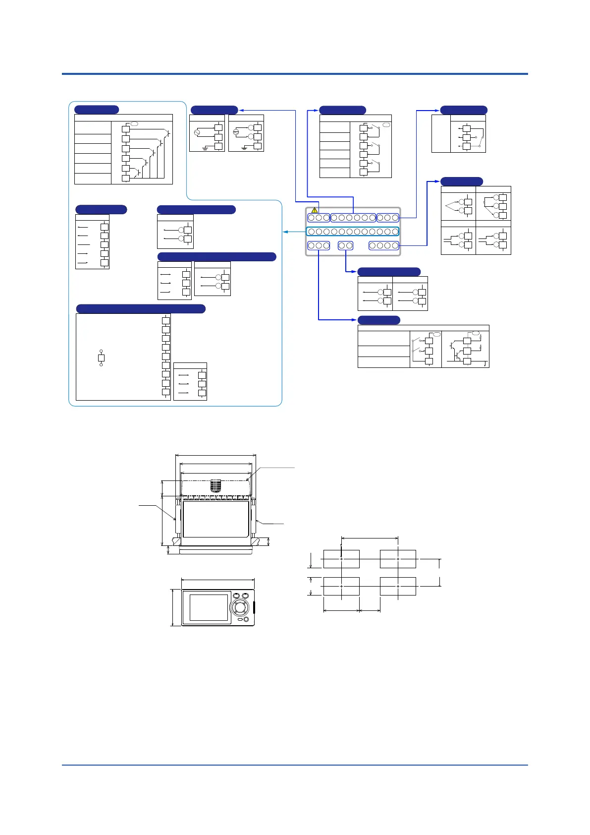
n Terminal Arrangement
301-312
201-212
101-112
212 2 11 210 208 207 204 203
112 111 110 109 106 105 104108 107 103
202 201
102 101
306 305 304 303 302 301312 311 310 309 308 307
E1-terminal area
PV
PV input
(Equipped
as standard)
TC input
+
-
202
203
RTD input
A
B
b
201
202
203
Voltage (mV, V) input
+
-
202
203
Current (mA) input
+
-
203
204
Factory default: PV input type is undefined.
RET
Retransmission output
(Equipped as standard)
Retransmission output
4-20 mA DC or
0-20 mA DC
+
-
Default: 4-20 mA DC
Default: PV
retransmission
Load resistance 600 Ω or less
207
208
15 V DC loop power supply
14.5-18.0 V DC
(Max. 21 mA DC)
+
-
207
208
Can be used for 15 V DC loop
power supply when not used for
retransmission output.
ALM
(Equipped
as standard)
Contact output
External contact output (relay)
AL3
AL2
AL1
Relay contact rating: 240 V AC, 1 A
30 V DC, 1 A (resistance load)
Alarm-3 output
(PV high limit)
Alarm-2 output
( PV low limit)
Alarm-1 output
PV high limit
Common
Common
Common
UM
104
105
106
107
108
109
ALM4
Contact output
Contact rating: 250 V AC, 3 A
30 V DC, 3 A (resistance load)
AL4
(24 V AC/DC power supply:
Option code /DC)
Power supply
Allowable range:
100-240 V AC (+10%/-15%)
(free voltage)
50/60 Hz shared
100-240 V AC power supply
N
L
110
111
112
24 V AC/DC power supply
-
+
110
111
112
N
L
+
24 V DC loop power supply
21.6-28.0 V DC
(Max. 30 mA DC)
-
24 V DC loop power supply
(Suffix code: Type 2=0 or 2
and with option code
/LP)
305
306
LPS24
RS-485
SDB(+)
SDA(-)
RDB(+)
RDA(-)
SG
RS
-
485 communication
301
302
303
304
305
RS485
(Suffix code:
Type 2=1 and
without option
code /LP)
(Suffix code: Type 2=3)
Contact output
External contact output
DO14
DO15
DO13
DO12
DO11
COM
Common
UM
301
302
303
304
305
306
DO
Transistor contact rating: 24 V DC, 50 mA
The function of each contact output can be changed.
Alarm-6 output
( PV low limit)
Alarm-5 output
(PV high limit)
Alarm-8 output
( PV low limit)
FAIL
Alarm-7 output
(PV high limit)
DI
(Equipped as standard)
Contact input
Contact rating: 12 V DC, 10 mA or more
External contact input
DI2
DI1
COM
Common
DI2
DI1
COM
+5V
+5V
No-voltage
contact
Transistor
contact
UM
UM
210
211
212
210
211
212
The function of each contact input can be changed.
DI1=ON: PV peak and bottom
values reset
OFF → ON: Latch release
101
102
Relay contact output
103
NC
NO
COM
Alarm-4
output
( PV low limit)
AL4
CC-Link communication (with Modbus master)
(Suffix code: Type 3=3)
FG:
Flame ground
SLD:
Shield
DG:
TX/RX signal ground
DB:
RX/TX signal
- signal
DA:
RX/TX signal
+ signal
CHK(red)
(Lit: User profile error/Adress error, Unlit: Normal)
L ERR(red)
(Lit: Communication failure(CRC error), Unlit: Normal)
L RUN(green)
(Lit: Normal, Unlit: No carrier detected/Communication timeout)
Not used
301
302
303
304
305
306
307
308
309
RS-485
RSB(+)
RSA(-)
SG
310
311
312
DB
DA
110Ω
CC-L
If the UT is located at the end of a
segment for the CC-Link
communication wiring,terminating
resistors are separately needed.
These are to be prepared by
users. (110 Ω: 1 pc.)
RS-485
RSB(+)
RSA(-)
SG
RS
-
485 communication/24 V DC loop power supply
+
24 V DC loop power supply
21.6-28.0 V DC
(Max. 30 mA DC)
-
301
302
303
305
306
RS485/LPS24
(Suffix code: Type
2=1 and with
option code /LP)
(Suffix code:
Type 2=1, 2
or 3)
n External Dimensions and Panel Cutout Dimensions
UM33A
Unit: mm (approx. inch)
Normal tolerance:
±(value of JIS B 0401-1998 tolerance class IT18)/2
96 (3.78)
48 (1.89)
20 (0.79)
65 (2.56)
11
(0.43)
Terminal cover
Bracket
94.6 (3.72)
91.6 (3.61)
105.2 (4.14)
1 to 10
(0.04 to 0.39)
(panel thickness)
(25) (0.98)
(53)
(2.09)
• General mounting
145 (5.71)min.
+0.03
0
(3.62 )
+0.6
0
45
+0.02
0
(1.77 )
+0.8
0
92
 Loading...